
Lessons learned while building crossbar interconnects
Okay, I’ll admit it, I’ve never used AXI for anything other than accessing DDR3 SDRAM memory. Even for that I tend to use a Wishbone (WB) to AXI bridge.
I have, however, looked for posts on both Digilent’s and now Xilinx’s forums that I might be able to answer. It seems that Xilinx’s answer to most design problems is to create either a MicroBlaze CPU or an ARM CPU (within a Zynq), that you then connect to the rest of your design using their interconnect.
 |
Xilinx’s interconnect is a general cross bar switch. It “connects one or more AXI memory-mapped master devices to one or more memory-mapped slave devices.” In general, a crossbar switch allows any number of bus masters to access any number of bus slaves with the (general) rule that only one master can talk to any given slave at a time.
This is all fine and dandy, but what happens when you want to simulate a design that has an AXI crossbar within it? Xilinx’s crossbar is proprietary. It won’t run in Verilator. Of course, their CPU is also proprietary, but we’ll leave that as a topic for a different discussion.
I recently had the opportunity to investigate how to build a crossbar switch of my own. I built three of them: a Wishbone crossbar, an AXI-lite crossbar, and a full-up AXI4 crossbar. Today, I thought I might share several of the more important points of these designs, and perhaps even some lessons I learned while building them.
Crossbars and AutoFPGA
My own interest in building a crossbar stems from my work with AutoFPGA. AutoFPGA takes a series of bus components, and connects them all together–much like either Vivado or Quartus does but without the graphical user interface. Each component is given its own address, a set of dedicated bus connection wires, and then connected to a user-selected bus.
This works great … when it works.
Sadly, I’ve had to work through some times when it hasn’t worked for me. Often, I’ve mis-connected a slave to the interconnect–perhaps not ANDing the address selection wire with the strobe, perhaps swapping the stall and acknowledgment signals, whatever it is I’ve often ended up needing to debug a piece of a design where the formally verified core meets some “verified-by-simulation” logic.
My ultimate goal is to avoid these problems by formally verifying all of the parts and pieces of any design I create, to include those parts that AutoFPGA generates.
 |
One of my first problems is that my favorite interconnect design, the same basic interconnect AutoFPGA builds, has a couple of limitations. First, it can only handle a single bus master at a time. Multiple bus masters need to go through an arbiter first before they can get access to the bus. We’ll come back to this again in a moment. Second, that interconnect offers no protection against the case where a bus master crosses from one slave to another during a single bus interaction, as Fig. 2 illustrates on the left. In this illustration, the first bus slave responds two cycles after the strobe while the second slave responds one cycle later. The responses might end up colliding, as shown in the figure, or even out of order. Worse, the third problem has to do with bus errors. If a bus error is generated as I have things set up, the bus master will never know which request generated the bus error and which request(s) have completed.
I was curious to know if I could do better.
At least, that was my first reason for being interested.
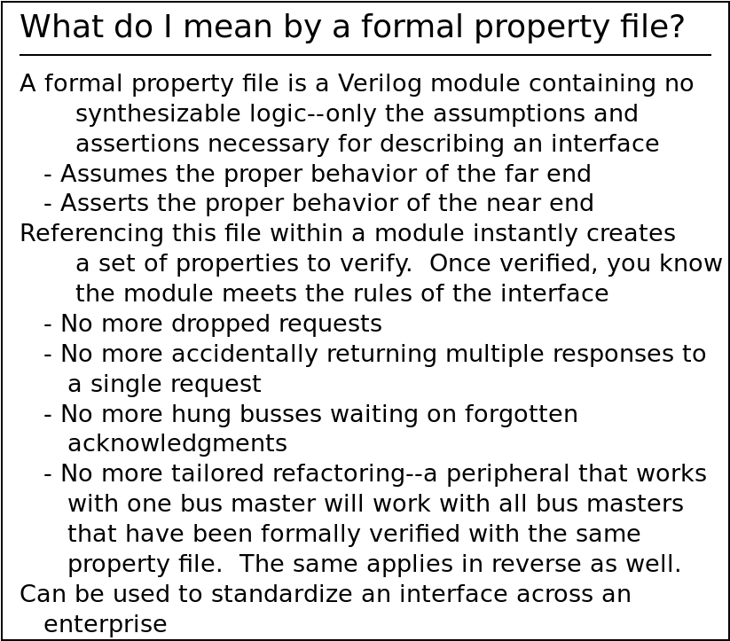 |
Eventually, a second reason came into play as well: Interconnects, like bus bridges in general, make ideal tests of formal bus property files. Because you need the properties for both the slave and the master, you essentially have to verify your properties back to back. Are the master bus property assumptions sufficient to drive the slave? Are the slave bus assumptions sufficient to satisfy the master’s assertions?
Finally, my last basic reason was that this interconnect work was a lot of fun. Indeed, I found them building these interconnects, and particularly formally verifying them, to be a rather addictive challenge–even if it’s quite a time consuming one. Hey, we all have our hobbies, right?
What is a Crossbar?
Wikipedia describes a crossbar as a two-dimensional electrical structure where the source comes in from one direction, and the outgoing connections go out a second. While there’s no picture offered currently on wikipedia, I’m going to use Fig. 4 as my attempt to capture and explain this concept.
 |
In this figure, you can see a set of incoming electrical connections at the top, and a set of outgoing electrical connections on the right. At every crossing, there’s a switch which may be closed to create a connection between any given master and slave combination.
There’s two other things to note from this figure. First, note that any
of the incoming signals can be connected to any of the outputs. Second, note
that for an NxN array, all N sources can be connected to a different
sink.
Bus interconnects are very similar conceptually. A series of bus masters are available as sources to drive one of several bus slaves. The biggest difference is that buses typically have many wires associated with them, and some of those wires are driven with return values by the slave. For example, a 32-bit AXI bus requires roughly 164 separate wires to drive the slave, whereas the slave will respond with another 50 wires returned in response. The WB. bus is both much simpler, and not nearly so full featured. Wishbone transactions, therefore, can be accomplished with only 106 separate wires, of which 71 are used to drive the slave and 35 are returned in response.
As for how you might use one of these, consider as an example that the typical ZipCPU design that has at least four separate bus masters:
-
The instruction fetch unit
-
The data memory port, handling any load or store instructions
-
A DMA data transfer port
-
A debug port, through which the CPU can be stopped, stepped, or reset and its registers may be read.
Some of my ZipCPU designs have more masters as well, for example:
-
A Video display controller that needs to read from memory in order to create a pixel stream
-
A spectrogram raster, that writes FFT results from captured data to the memory
As I’ve currently built most of my
ZipCPU designs, I’ve used 2:1
arbiters
such as this
one
followed by a 1:N interconnect, as illustrated by Fig. 5. (I did build a 4:1
arbiter
once, but as I recall I’ve yet to use it.)
 |
Sadly, that means that any bus master can starve another by simply hogging the port.
To see how this might happen, consider an example from one of my first FPGA projects what it would take to drive a video stream from a Basys3 board. The video driver needed access to the flash to read (and then decompress) pixels so that they could be displayed on VGA output. (There wasn’t enough RAM on or off chip for a proper screen buffer.) Now imagine that at the same time, the CPU wants to read instructions from block RAM: the video controller needs the flash, and the CPU needs the block RAM. By going through an N:1 arbiter first, or rather several 2:1 arbiters as I had actually implemented it, any time the CPU’s block RAM request would get through the arbiter it would then force any video requests to stall. Worse, they might need to wait so long that the video can’t read its pixel memory fast enough to display it.
This particular design was from before AutoFPGA. The solution I eventually chose, shown in Fig. 6 below, was to place the video memory controller after the main interconnect in order to disconnect the CPU from video memory if it didn’t need it.
 |
Of course, this will only ever work as long as the video controller only ever needs access to a single peripheral–in this case the flash.
If, on the other hand, the CPU could access the block RAM at the same time the video controller could access flash, then you have a crossbar—or at least that’s the idea.
With my new flash controller, this might no longer be an issue–but it certainly was back then with the older controller. On the other hand, with the old flash controller, I could only ever control a 640x480 screen–with the newer flash controller I might be able to handle some better screen resolutions if I ever returned to the project.
The key: an NxM Arbiter
When building a
crossbar, everything
comes down to the
arbiter.
The arbiter
has N ports for N masters, and M ports for M slaves. Somehow, then,
a slave needs to get its data from one of the masters. But which master?
That’s the task of the
arbiter.
There are several rules to the arbiter in a crossbar.
-
Rule: The bus protocol must be obeyed.
This is easily checked: all it requires is attaching a set of formal bus properties to every incoming or outgoing connection. Since I have bus properties for WB, AXI-lite, and even AXI, I could easily verify that each of my WB crossbar, AXI-lite crossbar, and AXI crossbar maintained these properties for each connection.
Having
NMidentical master connections andNSidentical slave connections naturally lent itself to a lot offorloops within the design. Normally I avoidforloops within digital design like the plague. In this case, there was no way around it if I wanted the interconnects to have a programmable number of master and slave connections.To help deal with this, I used either the
genvarindexNor equivalently the integer indexiNto refer to a connection to a bus master, while I used eitherMoriMto refer to a connection to a bus slave. I’ll refer to these indexes often later, so rememberNxM:Nwill reference one of theNconnections from theNMbus masters, whereasMreferences one of theNSoutgoing connections to bus slaves.
 |
-
Rule: No more than one master can be connected to any particular slave.
I used a 2-dimensional
grantvariable to help express this. This is most easily understood by examining Fig. 7 on the right. Imagine that each switch’s status was represented by a single bit in this array. In my terminology,grant[N]represents all of the connections associated with all of the slaves that might connect to masterN, shown in Fig. 7 as a vertical bar. Fig. 7 shows what would happen ifgrant[0][2]were set, connecting master numbered0to slave number2.Using this 2-D
grantarray, I could easily express this property that no more than one master could ever be connected to more than one slave asassert($onehot0(grant[iN]));for every value of the master index,iN.In the AXI interconnects I’ve built, whether the full AXI4 interconnect or AXI-lite interconnect, I used two grant variables,
wgrantfor writes andrgrantfor reads, since the AXI protocol allows both writes and reads at the same time.
 |
This wasn’t enough to keep the synthesized logic simple and low
cost,
so I created two other structures. The first of these, mgrant[iN], was
true if a particular master had been granted access to a slave–any slave.
Essentially, mgrant[iN] was equivalent to the “OR” of all of the elements
in the grant array for a particular master, |grant[iN].
The second structure was mindex[iN], which contained the index of the slave
that master iN was connected to. Hence, if ever mgrant[iN] was true,
then it must also be true that grant[iN][mindex[iN]] was also true.
Perhaps you may recall the post discussing why this approach was so
necessary from
some time ago. This index-based reference was my solution to that problem.
This “solution” naturally led to another problem, what if you only have for
example 5 slaves? How many bits should be used for each mindex value?
Well, three obviously. However, that also meant that any time a value was
referenced using the index, such as slave_ack[mindex[N]], that a full 8
values needed to be defined–even if I knew that only the lower 5 would be
used.
All of these various data structures are tightly connected. As I mentioned
above, mgrant[iN] |-> (grant[iN] == 1<< mindex[iN]). There was also the
corollary, that !mgrant[iN] |-> (grant[iN] == 0). This helped to make
certain that any logic I created kept these values properly synchronized.
 |
-
Rule: No more than one slave can be connected to any master. Any unconnected slave should neither receive requests nor send replies.
To capture this, I created two new values:
sgrant[iM], which would be true if slaveiMhad been assigned to a master. Remember howmgrant[iN]was true if any switch in the columns of Fig. 2 above was closed?sgrant[iM]is the same thing, only acting across the rows.sindex[iM]was the slave side corollary for the master index,mindex[iN], so that any timesgrant[iM]was true, thengrant[sindex[iM]][iM]must also be true. (That’s what the?is intending to express in Fig. 9–evaluated across all masters. No, this is not valid syntax in any language I am familiar with, but it fit in the figure.)Put together, any time
grant[N][M]was true, then masterNwas connected to slaveM. In that case, bothmgrant[N]andsgrant[M]would be true. Further,mindex[N]would beM, andsindex[M]would beN.Yes, keeping track of all of these values,
grant,mgrant,mindex,sgrant, andsindextook a lot of accounting. As I mentioned above, formal methods really helped.
 |
-
Rule: If a master requests an address that doesn’t belong to any slave, the interconnect must send a bus error in response. Further, it must not send the bus error response until any other valid responses have been returned, so enforcing a strict ordering of operations on the bus–something I didn’t have before.
This necessitated the creation of a special set of slaves, internal to the interconnect, which would respond to any bus errors. That meant that the slave index,
Mwouldn’t just go from0toNS-1, but rather toNSin order to reference the “no-peripheral mapped to this address” slave. You can see these extra slaves illustrated in Fig. 10 on the left.This special slave ID was unusual, since every master could connect to the error slave
NSat the same time. It’s as though there really wereNS+NMslaves, such as are shown in Fig. 10, rather than just theNSslaves connected to the right of the interconnect. That way two masters can be receiving bus error responses at the same time without needing to wait for access to the special bus error slave.
-
Rule: The interconnect can’t change the grant for a given master while that master is waiting for a response from a slave.
This requires counters. Every request accepted into the crossbar needs to increase that counter by one, whereas every response needs to decrease the counter by one. Once the counter reaches zero, the interconnect can tear down a given connection and set up a new one.
Checking for whether or not the counter is empty is quite straightforward, and I kept a set of flags I called
mempty[N], one for every master, to indicate that there were no outstanding returns pending for that master.Before we leave this topic, though, let me ask: have you thought about what would happen when the counter overflows? I think we can all agree that would be bad, but how should it be prevented?
The easy answer would be to just add more bits to the counter to prevent this from ever happening in the first place. I mean, realistically, what’s the likelihood that that a 32-bit counter of outstanding transactions would ever overflow? How about a 64-bit counter overflowing?
I chose a different answer. I chose instead to keep track of when the counter was full, which I kept track of in another array
mfull[N], and to stall a given master if accepting another transaction would cause the counter to overflow. This wasn’t as easy as it sounds, since it took a clock to stop things before I made the skid buffers external. That meant checking for when the counter was near overflow, and stalling if there was already something in the pipeline at that time. Once I made the skid buffers external, this all got much easier.There’s also an unfortunate consequence of this rule: if ever a slave misbehaves and doesn’t return a response, both the master granted access to that slave and any other master attempting to access that slave will be locked until a design reset. Perhaps you’ll remember when I discussed having that problem in a DE-10 Nano board. Finding a bug is a challenge when the only way to get the board to respond to you again is to reset it knowing that doing so will wipe away the information you need to find the bug.
 |
-
(Implementation Option:) A bus interconnect may generate an error if ever a slave doesn’t respond to a request within a given amount of time.
This follows from some ugly lessons I’ve had in the past when building bus components. Because I use a bus based “scope” to debug my design, if ever a bus component didn’t respond to the bus, the master might get stuck waiting for a response–and so I’d never be able to access my “scope” to know what was going wrong.
To deal with this, every Wishbone bus structure I’ve built includes a counter with a timeout. That way, if an errant slave refused to respond to a request (this was pretty common before I started working with formal methods), the design wouldn’t freeze and I could still use the design to discover what the fault was.
Sadly, the way the AXI protocol is structured, this is really hard to do. Eventually, I created a separate AXI bus component that I could use to bridge between the “trusted” bus master side and any untrusted slave, returning a bus error on any violation of the bus protocol by the slave. Unfortunately, as currently built, this AXI bus fault isolator also limits the throughput of the bus–although not nearly as bad as Xilinx’s demo implementations do. Perhaps I’ll be able to come back later to fix this.
 |
-
Rule: Every connection that can stall needs to be connected to a skid buffer, as shown in Fig. 12 above. All of my crossbars have an incoming skid buffer, while only the AXI and AXI-lite crossbars have return channel skid buffers as well.
Sadly, these sub-module skid buffers weren’t part of my initial design approach. In hind sight, they should’ve been.
Initially, I instantiated every one of the skid buffers by hand within each crossbar I created. I then verified each crossbar from the standpoint of the external connections. This threw all of my counters off, since I had to create an equation mapping the number of outstanding transactions from the perspective of each master, to the number of outstanding transactions from the perspective of each slave, and the skid buffers got in the middle of that. If I failed to do so, the design would fail induction.
This book-keeping was quite painful.
On the other hand, once I created and verified a separate skid buffer module, I went back and tore apart all of those painful formal properties and rewrote them for simplicity. Now, when verifying the crossbar, the skid buffers have been removed and replaced with simple pass-through logic. The proof, I’ve judged, is just as valid–since the skid buffers have already been verified separately.
This almost worked, too. There was one problem: The bus abort capability I’ve written into all of my WB implementations. Eventually, I convinced myself with a bit of bounded model checking that this was working, although I haven’t come back to simulate these crossbars (yet) to see how they work.
Some particular bus structures have more or less requirements than others. For example, the way I implement WB, I insist that the cycle line be dropped following any bus error. This then implements a bus abort, forcing any pending upstream requests to be aborted and leaving any pending transactions in an uncertain state. Unlike WB, AXI doesn’t support any aborts. However, AXI also has two write channels that need to be synchronized: an AXI write address channel and an AXI write data channel–something Wishbone doesn’t need to deal with. The AXI arbiter, whether full or lite, needs to stall any write data channels in order to wait for the address to be given before it knows what slave to connect the write data channel to.
Still, most of the arbitration code is the same across all three of the crossbars. Care to take a peek?
Examining the Arbitration Code
Let’s look at the Wishbone crossbar’s arbiter and see how it’s done. Both the AXI and AXI-lite crossbars have similar structures and logic, although in those cases the logic is duplicated in order to handle the separate read and write channels.
The first step is to find out what master is requesting which slave. Since this
code is common to all three
interconnects,
it has been separated into its own
file, addrdecode.v.
The entire
address
decode operation is driven by the SLAVE_ADDR and
SLAVE_MASK parameters.
These two parameters are each one-dimensional implementations of what
should properly be a 2d array. There’s one entry of AW (address width) bits
per slave. In order to match an
address,
the master’s address
request must match the slave’s
address
in SLAVE_ADDR for every bit where SLAVE_MASK is true.
We’ll start first with the none_sel flag though. This flag is used to
indicate that the requested
address
doesn’t match any slave’s
address
range. To do this, we’ll run a check through a for loop, checking
whether or not the requested
address
matches any of the possible
address
requests. We’ll start by setting none_sel high if ever there’s a valid
request, indicated by i_valid, and then clear it if any slave is found who’s
address matches.
	always @(*)
	begin
		// Let's assume nothing's been selected, and then check
		// to prove ourselves wrong.
		//
		// Note that none_sel will be considered an error condition
		// in the follow-on processing.  Therefore it's important
		// to clear it if no request is pending.
		none_sel = i_valid;
		for(iM=0; iM<NS; iM=iM+1)
		begin
			if (((i_addr ^ SLAVE_ADDR[iM*AW +: AW])
					&SLAVE_MASK[iM*AW +: AW])==0)
				none_sel = 0;
		end
	end
We can then populate a request[M] array structure, so that
request[M] will be true if and only if the address of the transaction
we are examining is requesting access to slave M.
	always @(*)
	begin
		for(iM=0; iM<NS; iM=iM+1)
			request[iM] = i_valid
				&&(((i_addr ^ SLAVE_ADDR[iM*AW +: AW])
					&SLAVE_MASK[iM*AW +: AW])==0);

		//
		// request[NS] indicates a request forr a non-existent
		// slave.  A request that should (eventually) return a bus
		// error
		//
		request[NS] = none_sel;
	end
That’s all of the hard address decoding work. The rest of the address decoder just handles how these values are to be returned–whether they are to be registered, or held at zero when nothing is requested, or both.
Once the addresses have been decoded to determine which slave is requested,
the next step is to
arbitrate
among potentially multiple masters all wanting access to the same slave.
For my implementations, I chose to do
arbitration
on a priority basis. In other words, if a
master N2 requests a slave M, the request will not be granted if some
other higher priority master, we’ll call it N1 where N1 < N2, has also
requested the same slave at the same time. The array of requested values,
defined below, captures this idea. If requested[N][M] is true, then some
other master with a higher priority than master N has requested access to
slave M.
	always @(*)
	begin
		for(iM=0; iM<NS; iM=iM+1)
		begin
			// For each slave
			requested[0][iM] = 0;
			for(iN=1; iN<NM; iN=iN+1)
			begin
				// This slave has been requested if a prior
				// master has requested it
				//
				// This includes any master before the last one
				requested[iN][iM] = requested[iN-1][iM];
				//
				// As well as if the last master has requested
				// this slave.  Only count this request, though,
				// if this master could act upon it.
				if (request[iN-1][iM] &&
					(grant[iN-1][iM]
					|| (!mgrant[iN-1]||mempty[iN-1])))
					requested[iN][iM] = 1;
			end
		end
	end
Notice here that I cross-checked the request against those masters that could
properly respond to it. That way if a master N1 requests slave M1,
but hasn’t yet finished getting the responses from slave M2 that it is
already connected to (i.e. mempty[N1] is clear), then a lower priority
master such as N2 will not be prohibited from connecting to M1.
Now that we have our address decoding and basic book-keeping out of the way, we can look into what the actual arbitration requires. In this design, arbitration is done on a master by master basis using a variety of different variables, some of which I’ve already highlighted and defined above.
	//
	// Arbitrate among masters to determine who gets to access a given
	// channel
	generate for(N=0; N<NM; N=N+1)
	begin : ARBITRATE_REQUESTS

		// This is done using a couple of variables.
		//
		// request[N][M]
		//	This is true if master N is requesting to access slave
		//	M.
		//
		// requested[N][M]
		//	True if some other master, prior to N, has requested
		//	channel M.  This creates a basic priority arbiter,
		//	such that lower numbered masters get access before
		//	a greater numbered master
		//
		// grant[N][M]
		//	True if a grant has been made for master N to access
		//	slave channel M
		//
		// mgrant[N]
		//	True if master N has been granted access to some slave
		//	channel, any channel.
		//
		// mindex[N]
		//	This is the number of the slave channel that master
		//	N has been given access to
		//
		// sgrant[M]
		//	True if there exists some master, N, that has been
		// 	granted access to this slave, hence grant[N][M] must
		//	also be true
		//
		// sindex[M]
		//	This is the index of the master that has access to
		//	slave M, assuming sgrant[M].  Hence, if sgrant[M]
		//	then grant[sindex[M]][M] must be true
		//
Before assigning any slaves to a given master, the
arbiter
needs to know whether any current connection needs to remain connected and
unchanged. In other words, if master N has already been granted
access to slave M, has master N finished its business with that slave?
For that, we’ll check if this master is making additional requests of
the same slave that it has already been assigned to. In the simple check below,
we check every master N and every slave iM. If a grant has already been
made between master N and slave iM, and a new transaction request from
that same master N is being made to the same slave slave iM, then we want
to maintain this connection.
		always @(*)
		begin
			stay_on_channel = |(request[N] & grant[N]);
That’s only the first reason why we might wish to stay on the channel and maintain a given grant. The other reason why we’d want to maintain a given grant is if we are still expecting returns from it.
Handling this requires counting the number of transactions that have been
issued, minus the number of acknowledgments that have been returned. A
variable mempty[N], set from the master’s perspective, contains whether
this count is zero or not. Hence if this master has never been granted
access to a slave, or if a grant has been made but we’re still waiting
for responses, then we need to stay_on_channel.
			if (!mgrant[N] || !mempty[N])
				stay_on_channel = 1;
		end
The next step is to determine if the requested channel is even available.
In this case, if master N is requesting channel iM, that is if
request[N][iM] is true, and no other master has currently been granted access
to slave iM so that sgrant[iM] is false, and no other (prior) masters
are also requesting this channel, indicated when requested[N][iM] is low,
then this channel is available for reassignment.
		always @(*)
		begin
			requested_channel_is_available =
			|(request[N][NS-1:0] & ~sgrant & requested[N][NS-1:0]);

			//
			// The bus error channel is always available
			//
			if (request[N][NS])
				requested_channel_is_available = 1;
			// ...
		end
With all of this background work, we are now ready to make a channel grant.
		initial	grant[N] = 0;
		initial	mgrant[N] = 0;
		always @(posedge i_clk)
		if (i_reset || !i_mcyc[N])
		begin
			grant[N] <= 0;
			mgrant[N] <= 0;
We’ll only ever adjust any grant given to a particular master if that master
doesn’t need to stay_on_channel. In that case, the master can be granted
access to any channel that is available, i.e. requested_channel_is_available
is true. Finally, if the master is attempting to make a request of another
channel, then we’ll release the channel grant.
		end else if (!stay_on_channel)
		begin
			if (requested_channel_is_available)
			begin
				mgrant[N] <= 1'b1;
				grant[N]  <= request[N];
			end else if (m_stb[N])
			begin
				// Master is requesting access to another
				// slave, one that isn't yet available.
				//
				// Release the grant so another master
				// can use it.
				mgrant[N] <= 1'b0;
				grant[N]  <= 0;
			end
The new variable introduced here, m_stb[N], is simply the strobe signal
output coming from the address
decoder
shown in Fig. 12.
Since we’ve assigned slave number NS to reference the “no slave at that
address” channel, this simple logic above handles that grant as well.
I should also point out, getting this right took several iterations, and a bit of learning along the way. Earlier versions of this logic, such as this one for example, were horrendous to follow and/or maintain. Getting the design to be properly simple–that’s taken some work.
From here on out, the rest of the arbiter’s work is book-keeping.
Well, not quite. Did you notice how many clocks were required for that
processing? One. We calculated quite a few pieces of logic from requested,
stay_on_channel, requested_channel_is_available, all the way to
grant and mgrant all on the same clock cycle. Did you catch that?
That’s a lot of processing for a single clock. As a result, the more
slaves and the more masters get connected to this
crossbar
arbiter,
the slower it will become. To keep this from ballooning out of control, both
the skid buffers
and the address
decoder
have configuration options to add clock cycles in order to break up the
any paths leading into to this critical path.
There’s also a big difference at this point between
AXI and
Wishbone.
Unlike Wishbone,
AXI
has separate channels for write
address
and write data.
According to the specification, the data in these channels may arrive at any
time and in any order. The write data, for example, might arrive first
and then the write address
or vice versa. However, the data cannot be routed to the correct slave until
the address is known and has
been properly decoded. Therefore the
interconnect
must stall the write data channel, should it arrive at the
crossbar early, until the write
address
is provided, decoded, and a grant is given. Once a grant has been provided,
it must remain active until all of the write data associated with that grant
has been accepted. With
AXI,
that means that the
arbiter
must wait until the WVALID & WLAST signal has been received before
any write grants referencing this master-slave combination may change. With
AXI-lite,
that also means that the
arbiter
must wait until the write data channel has caught up to the write
address
channel before adjusting any write grants.
Setting the slave outputs
At this point, all the difficult processing has been done. All that remains is to reap the rewards from this hard work.
For example, we can now set our
bus
outputs to drive the various slaves. To do this, we’ll loop through
every slave channel, and adjust the associated
bus
information any time the channel isn’t stalled. Further, we’ll use the
sindex[N], the slave’s index array indicating which master is associated
with this slave, to set these values.
	generate for(M=0; M<NS; M=M+1)
	begin
		always @(posedge i_clk)
		begin
			// Values can change any time the slave isn't stalled
			if (!s_stb[M] || !s_stall[M]) begin
				o_swe[M]              <= m_we[sindex[M]];
				o_saddr[M*AW   +: AW] <= m_addr[sindex[M]];
				o_sdata[M*DW   +: DW] <= m_data[sindex[M]];
				o_ssel[M*(DW/8)+:DW/8]<= m_sel[sindex[M]];
			end

		end
	end endgenerate
These particular values, however, are the easy ones: they aren’t the control
signal values, but rather the values that are qualified by the control signal
values themselves. As a result, if the valid signal (o_sstb[M] for
WB,
xVALID for
AXI)
is low, these become don’t care values.
The control signals are a touch more complicated.
First, in order to support a bus abort capability, we abort any transaction following either a reset or a bus error return from the slave.
	generate for(M=0; M<NS; M=M+1)
	begin

		initial	o_scyc[M] = 0;
		initial	o_sstb[M] = 0;
		always @(posedge i_clk)
		if (i_reset || s_err[M])
		begin
			o_scyc[M] <= 1'b0;
			o_sstb[M] <= 1'b0;
The last step of implementing the bus abort is to drop the slave’s Wishbone cycle line any time the master drops his.
		end else if (sgrant[M])
		begin

			if (!i_mcyc[sindex[M]])
			begin
				o_scyc[M] <= 1'b0;
				o_sstb[M] <= 1'b0;
Otherwise, if we aren’t aborting a transaction and a grant has been made then we must be in the middle of a valid transaction. The slave’s cycle line needs to be set to reflect that.
			end else begin
				o_scyc[M] <= 1'b1;
The strobe signal is more complicated.
As you may remember, the
WB
strobe signal indicates a transaction request, whether for read or write, and
that it is roughly analogous to the
AXI)
AxVALID signals. The first rule of any request is that the request cannot
change as long as another one is outstanding. For this reason, we wrap the
control logic so that any time o_sstb[M] && s_stall[M], that is any time
the slaves strobe and stall signals are both high, nothing gets changed.
If (!o_sstb[M] || !s_stall[M]) just reflects the opposite using
De Morgan’s laws, such
that bus
values may legitimately be changed without dropping any requests.
if (!o_sstb[M] || !s_stall[M])That was the easy part.
The difficult part about the strobe signal is that we can’t just set it to
the master’s strobe input, m_stb[sindex[M]]. We have to first check that
the master is still requesting this particular slave, such that
request[sindex[M]][M] is still true. Remember, one of the bugs we are hoping
to fix by creating this
arbiter
is associated with a master accessing a second
slave before the first has had a chance to respond. In this case, we can
check both by simply checking request[sindex[M]][M] since the request
signal will never be high unless m_stb[sindex[M]] is also high.
The unusual requirement is that we also need to check that the channel isn’t already too full. Remember the comment about using counters to count transactions, and the requirement that the counters cannot overflow? If the counter is about to overflow, then the channel is full. We can’t issue another transaction in that case, but rather need to wait for some returns to come back first.
					o_sstb[M] <= request[sindex[M]][M]
					  && !mfull[sindex[M]];
			end
Finally, if there’s been no grant to this slave at all, then both cycle line and strobe line’s can be cleared.
		end else begin
			o_scyc[M]  <= 1'b0;
			o_sstb[M]  <= 1'b0;
		end
	end endgenerate
We’ve now decoded the address, and connected the slave to the master requesting a connection. We’ve even sent the details of the request to the slave. What we haven’t done is return any of the details from the slave back to the master. That’s the next step.
Returning values to the master
There are two types of values that need to be returned to the master. The
first is are the acknowledgments and data returned from the slave. With
WB,
these are easy. We can use the mindex[] as a pointer to just
copy the slave’s return values to the master.
		for(N=0; N<NM; N=N+1)
		begin

			always @(*)
			begin
				m_stall[N] = 1;
				o_mack[N]   = mgrant[N] && s_ack[mindex[N]];
				o_merr[N]   = mgrant[N] && s_err[mindex[N]];
				o_mdata[N*DW +: DW] = s_data[mindex[N]];
The stall signal is a bit more involved, just because there are more reasons why we might stall. We default the stall signal to one, then allow it to be cleared if the we have an active grant to a given slave, and a request to that slave, and if that slave isn’t also stalled.
				if (mgrant[N])
					// Possibly lower the stall signal
					m_stall[N] = s_stall[mindex[N]]
					    || !request[N][mindex[N]];
However, if the channel is full–that is if our counter is near rolling over, then we need to stall this channel as well.
				if (mfull[N])
					m_stall[N] = 1'b1;
As with many things, there are exceptions.
For example, if the master has requested a non-existent address, or if the transaction has timed out, then we need clear the stall line, accept a transaction, and return a bus error.
				if (grant[N][NS] ||(timed_out[N]&&!o_mack[0]))
				begin
					m_stall[N] = 1'b0;
					o_mack[N]   = 1'b0;
					o_merr[N]   = 1'b1;
				end
Sadly, this timeout signal only works because of the bus abort capability implemented within the WB standard I use. It doesn’t work on the AXI crossbars.
Finally, if the master drops his cycle line, aborting any ongoing transactions, then we need to make certain that nothing more gets returned. Any ongoing transactions will be left in an undetermined state.
				if (!m_cyc[N])
				begin
					o_mack[N] = 1'b0;
					o_merr[N] = 1'b0;
				end
			end
		end
I use this bus abort capability primarily for two reasons. First, following any bus error, the master will naturally want to abort any ongoing transactions. This implementation was chosen from the perspective of a CPU. If a software program receives a bus error, the CPU doesn’t really care what other transactions might succeed or fail–the software program has already failed. This simplifies the cleanup. The same is true of the DMA: following any bus error, the correct answer is to abort any efforts at further transactions.
AXI, however, doesn’t have a way of signaling a bus abort condition, nor does it have a way of implementing one: every transaction request must receive a response. This includes burst read responses as well–the AXI bus is still required to return every beat of a burst read response even if all of them will indicate bus errors.
This lack of a bus abort makes implementing a timeout difficult. Imagine, if
you will, that the
interconnect
detects a broken channel. Perhaps the
AXI slave
has failed to return a response, or perhaps that response is to an
ID for which nothing is pending, or perhaps it sets the xLAST flag too early,
either way, there’s no way to recover since there’s no way to indicate to the
AXI slave that the master
wishes to discard anything it might still wish to respond to.
WB doesn’t have that problem since all the master needs to do is to deassert the cycle line for the slave to know to reset any transactions in progress.
The way to handle this properly is to assign a timeout counter to every AXI burst. Then, if the slave fails to respond or responds inappropriately, every response following is to be held as an error. This is how my AXI bus fault isolator worked initially. The reason for this approach is simply that there’s no way to know if a response, following an error of some type, is to be treated as a valid response or a continuation of the fault.
The problem with this approach is that there’s no way to recover.
This is why I went back and updated the AXI bus fault
isolator
to add to it the ability to reset the entire (broken) downstream core, using
the S_AXI_ARESETN signal. Once the downstream slave then comes back from
the reset condition, it is reattached to the bus. Until that time, as long
as it is either in the fault condition or in the reset condition, the AXI
bus fault
isolator
simply returns bus
errors for every transaction
request.
Composing slave and master properties
The last step of the crossbar design process was to formally verify that the design worked, or equivalently to verify that it still worked following any changes. Changes? Yes, I made a lot of changes along the way, especially as I learned more and more about how to do this.
The first and easy step in this process was to connect a formal bus property file to every connection coming in or going out of the crossbar, as shown in Fig. 13. We’ve already discussed this property file for both Wishbone and AXI-lite on the blog. In general, having such a file makes it really easy to verify that a given bus component obeys the rules of the road.
 |
The difficult part of this task is induction. In order to pass induction, the internal state variables of each formal property file need to be related to the registers within the design, and to the state variables found in each of the other formal property files.
For example, consider the
Wishbone bus.
The formal property file
maintains a counter of outstanding transactions in order to be able to make
certain that 1) every request gets a response, and 2) that no responses are
issued without a prior request. These counters need to be matched. For
example, suppose master N is connected to slave M, so that grant[N][M]
is true. In that case, the number of outstanding transactions from the
perspective of the master must be matched to the outstanding transactions
counter within the slave.
This isn’t as trivial as it sounds.
Transactions issued by the master might be waiting in the decoder. Similarly, transactions in any skid buffers need to be counted. In the end, you need to have an assertion that one value, based upon the master’s transaction counter, equals a similar value based upon the slave’s transaction counter.
Let’s see if we can make any sense of how this is done. Within
this design,
f_moutstanding[N] is the counter containing the number of outstanding
transactions from the perspective of the master, and f_soutstanding[M]
contains the same counter from the perspective of the slave.
The check itself is done across all masters.
	generate for(N=0; N<NM; N=N+1)
	begin : CHECK_OUTSTANDING

		// ...
The first step is to make certain that the master’s transaction count includes at least enough to keep our arithmetic from overflowing. This means that if there’s a valid transaction coming out of the decoder, and if the decoder outputs were registered, then it must be accounted for in the master’s count. Similarly, if the return response is being buffered, then there must be a value in the master’s counter accounting for the valid value in that buffer as well.
		always @(*)
		if (i_mcyc[N])
			assert(f_moutstanding[N] >=
				((OPT_BUFFER_DECODER && dcd_stb[N]) ? 1:0)
				+ (o_mack[N] && OPT_DBLBUFFER) ? 1:0);
We can now subtract these two values from the master’s counter to create
a new value, n_outstanding, containing the number of transactions that have
been sent to the slave.
		always @(*)
			n_outstanding = f_moutstanding[N]
				- ((OPT_BUFFER_DECODER && dcd_stb[N]) ? 1:0)
				- ((o_mack[N] && OPT_DBLBUFFER) ? 1:0);
The last step is to match this count to the slave’s count. So, we’ll
loop through all possible slave connections. For any bus master N
connected to slave M, this number of outstanding transactions is required
to match the number of outstanding slave transactions. Well, almost. The
slave hasn’t yet counted any transaction it hasn’t yet accepted. It might
also be that o_scyc[iM] (the slave’s cycle line) is low, or an error
received and so the slave has aborted its transaction but the master hasn’t
yet aborted it, etc., etc.
		always @(posedge i_clk)
		if (i_mcyc[N] && mgrant[N] && !i_reset)
		for(iM=0; iM<NS; iM=iM+1)
		if (grant[N][iM] && o_scyc[iM] && !i_serr[iM] && !o_merr[N])
			assert(n_outstanding
				== {1'b0,f_soutstanding[iM]}
					+(o_sstb[iM] ? 1:0));
The key here is that this assertion must be an assertion of equality. If the two counters are not related to each other exactly, the induction engine is guaranteed to fail. (I should know–I keep trying to use inequalities for this check, and then getting corrected by the solver.)
With AXI-lite, this check is just a touch more involved. Unlike Wishbone, there’s no bus abort. Unlike Wishbone which has only the one counter, AXI-lite requires counters for the number of outstanding read transactions, write address and write data transactions. AXI has even more state to track, in order to make certain that the number of transactions with a given ID, and the number of beats per burst, all match the data within the interconnect’s internal registers.
Crossbar Options
One of the annoying realities of these separate
crossbars
is the options
they can be configured with. Sure, there’s the easy options: the number of
masters, NM, and the number of slaves, NS, are both configurable. The
address ranges
of the various slaves are configurable as well. Further, as you’ve gathered
from above, the size of the counters used to determine how many transactions
are outstanding is also adjustable. The size of this counter is controlled
by the parameter LGMAXBURST. After that, though, I started to get greedy.
The first option I created was the OPT_LOWPOWER option. This option is
common to all three of the
crossbars. The jury is still
out regarding whether this is useful or not (I haven’t measured it), however
many bus lines can travel long distances on a chip. If the lines can be held
at zero any time they are not in use, that is any time cyc is zero for
WB or AxVALID is zero
for AXI, then no energy
needs to be spent to charge those
lines. This comes at the cost of extra required logic, but I still think it
might help lower the overall power required. I’m looking forward to measuring
if this has any effect.
For the WB
crossbar,
there’s also an option to register the return values from the
slave, OPT_DBLBUFFER. There’s also the option of setting a timeout,
OPT_TIMEOUT, so that any return
that doesn’t come back in time for the timeout can be turned into an
error
and a subsequent bus abort. Here, I got greedy again. I added an additional
register to control whether or not a request should timeout before it even
gets to the slave. This I call a starvation timeout, and its an indication
that a particular master isn’t getting access to the slave fast enough.
Perhaps another master is hogging the slave. Perhaps it’s a well used slave
and this master doesn’t have enough of a priority. Either way, with the
starvation timeout parameter set, OPT_STARVATION_TIMEOUT=1'b1, each master
will be guaranteed a return in a fixed and known number of time-steps.
If only I could do that with AXI. Although I haven’t done that with the AXI-lite crossbar, that might be easy enough to be doable still.
One of the parameters the
AXI and
AXI-lite
crossbars share that the
WB crossbar
doesn’t have is a linger option, OPT_LINGER. The idea behind this option is
that if master N has just finished talking to slave M, then that connection
is likely to be needed again in the near future. Once the channel becomes
idle, therefore, the
arbiter
will wait OPT_LINGER clocks before removing the grant. If master N wants
to talk to slave M again, the grant is already there waiting for him and
he won’t have to wait for it. Of course, it will
only linger if no other master wants access to this particular slave. This is
therefore a useful, though optional, configuration parameter which might
impact performance.
Of course, the sad reality of any of these options is that the
crossbar really needs to be
verified
for every possible parameter setting. Hence verifying the
WB crossbar
requires 48 proofs (36 assertion based, 12 cover based), whereas the
AXI-lite crossbar
requires 12 proofs (6 assertion based, 6 cover based). The full
AXI crossbar,
as currently configured, requires 8 assertion based proofs. This is really
incomplete, since it doesn’t (yet) have a set of cover-based proofs
to show that not only will it not violate any properties, but that it can
actually properly complete transactions in the first place. For now, though,
you can just consider this last piece a work in progress–even though I’ve
done enough testing with various cover() checks to be confident that
the AXI
crossbar,
would work.
Xilinx’s Interconnect
Once I had formally verified my own
interconnects, I became curious
about how hard it might be to formally
verify Xilinx’s AXI
interconnect.
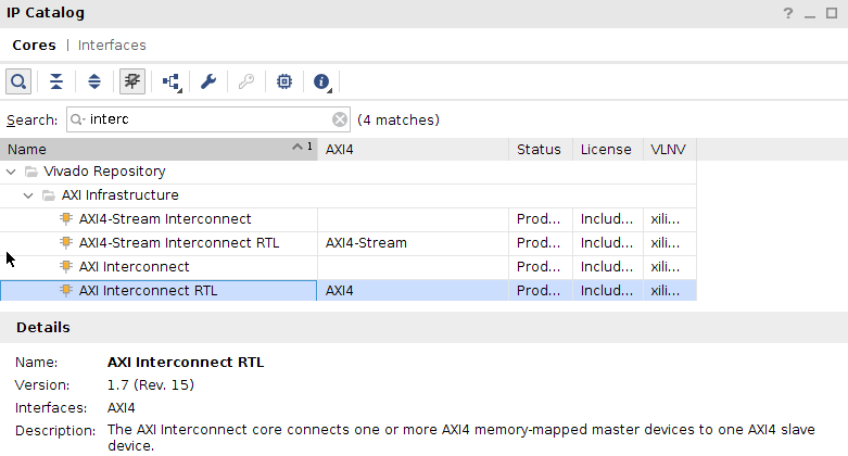
If you check out Vivado’s IP Catalog, you’ll find an entry for a
AXI interconnect RTL which, when instantiated, will create a Verilog copy
of their their
interconnect.
 |
I spent some time looking through this (after I’d built my own) and I’ve learned a lot from it.
First, they have two different types of
interconnects
implemented. The first type offers grants to slaves based upon read or write
requests. This is different from my own grants above which are based upon
either write requests or read requests. In other words, if you request
to read from a peripheral from this first type of
interconnect, you’ll get a
write grant as well. It’s not yet clear to me what will happen if you request
both read and write grants at the same time, though. This particular
interconnect ignores the AxID
values when routing–much like my
own. Not only
that, this version of Xilinx’s
AXI
interconnect might easily
mask the AXI bugs found
in their demonstration slave core.
The other type of
interconnect
they support grants access to both read and write requests separately, and
uses the AxID field to route the returns back to the slave that requested
the transaction. This was how I had always thought an AXI
interconnect would
be created–that is, until I tried building my own. The reason why I don’t
route bus returns based upon the BID or RID fields is simply because you’d
need another
arbiter–this
time for the return channel. The first
arbiter
already costs a minimum of two clock cycles of latency. This second
arbiter
would need to consume a similar amount of resources on the return. Adding
four clocks to every transaction seems excessive. So, while it’s doable,
I didn’t find it worth the performance cost.
The other thing I found while browsing Xilinx’s
interconnect code, were a large
number of translators that could bridge from one bus type to another. Their
interconnect
it seems is capable of instantiating clock domain
crossing bridges, bridging from
AXI3 to AXI4,
AXI-lite
to AXI4,
AXI4,
to AXI-lite,
AXI4 with one size
AxID values to AXI4 with
another, and so on. It’s quite configurable, although the small budget
hobbyist should beware: each of these translations costs resources within
your design.
Of those bridges, the one that surprised me was the AXI-lite to AXI4 bridge. Whereas AXI-lite is a very capable protocol, capable of high speed operation just as fast if not faster than the full AXI4 protocol, Xilinx’s bridge code crippled the AXI4 generated transactions so that no more than one read or one write would ever be outstanding at any given time. The bridge also cost several clock cycles, which is unusual since an AXI4 transaction can be created from an AXI-lite transaction by fixing and ignoring the unused fields. No matter how I looked it over, I couldn’t see any reason for building their AXI-lite to AXI4 bridge in this fashion.
Perhaps this explains why the bugs in their AXI-lite demonstration core have gone unnoticed for so long?
The sad reality, however, of both of these observations is that some day Xilinx will update their interconnect, and all of a sudden a lot of AXI slaves, written based upon their demonstration code, will start failing.
I guess that means that if you haven’t started formally verifying your AXI bus components, you should start doing so now.
Conclusion
Building your own crossbar interconnect may be intense, but it is certainly possible to do. I will say this, though, I’m not sure I could’ve done it without the formal property files for either Wishbone, AXI-lite, or the AXI4 bus protocols.
I should also mention that the proofs themselves aren’t necessarily all that fast to accomplish. While the formal tools can often find bugs quickly, proving that there are no bugs can be much harder. As a result, my initial development on each of these crossbars was pretty quick. It then slowed down. At one point, it took over 50 hours to verify the AXI crossbar in one of its configurations. Creating submodules to contain the skid buffers really helped, dropping the maximum proof time down to 22 minutes. Sure, it takes time, but it’s quite doable.
The biggest thing I haven’t discussed about full crossbar interconnects is their logic cost. That full crossbar doesn’t come cheap, and certainly not for any sizable number of masters or slaves. Worse, the cost doesn’t scale linearly as the number of masters or slaves increases. Instead of opening that discussion now, let me simply invite you to take any of the arbiters discussed here and to build it using Yosys to see how much it will cost as you vary the parameters.
Finally, I would still like to come back to this topic and walk through some of my brand new AXI cores: the bus fault isolator, the AXI to AXI-lite bridge, the AXI-lite to AXI bridge, or perhaps even the Wishbone to AXI bridge that I use to get high speed access to the DDR3 SDRAM memory. These we’ll do if the Lord permits.
Thus saith the LORD, Stand ye in the ways, and see, and ask for the old paths, where is the good way, and walk therein, and ye shall find rest for your souls. But they said, We will not walk therein. (Jer 6:16)