
Building the perfect AXI4 slave
I’ve now already shared the story of the contract I was on some time ago, where I failed to achieve the performance I promised because I placed too many bus bridges between the ARM and the FPGA that shared the same die.
 |
The easy way around this problem would be to design an AXI interface to my data FIFO. At the time of the project, AXI was too complicated for me to understand. I had tried to build an AXI slave controller several times over, and failed every time.
 |
I recently returned to the task, but this time using formal methods. My first step was to build a formal property file to describe an AXI4 interaction, similar to the one we built for AXI-lite together. I learned several things along the way, too:
-
According to the AXI specification, “On master and slave interfaces there must be no combinatorial paths between input and output signals.”
Fig 3. Reading from a data FIFO 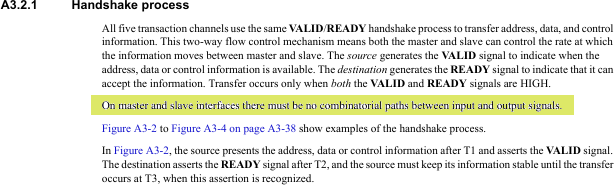
If you aren’t following me on twitter, then you’ve missed the discussion regarding the meaning of this sentence. I have taken it to mean that all AXI4 signals must be registered. Others have since pointed out that this reading is probably too strict. Perhaps a better reading is just that “combinatorial paths between input and output signals” are disallowed.
Since I already started with the interpretation that all AXI signals must be registered, I’ll stick with it here. Indeed, registering all I/O’s is not a bad thing as Eric LaForest of GateForge Consulting wrote,
Although having a combinatorial path will work (I have seen it on some Xilinx AXI IP), the resulting round-trip time on a ready/valid handshake worsens designs: Shaving a cycle here is not worth the reduced Fmax and harder P&R.
So there are good reasons to do this, even if I was mistaken that the specification required it.
This is then unlike the Wishbone designs I’ve done where the stall signal isn’t supposed to be registered. This also means that it will be really hard to touch any AXI signal without losing a clock due to delay.
-
I also discovered the problem I had been suffering from: write transactions don’t return one
BVALIDper element written, but rather oneBVALIDresponse per burst transaction. In other words, for everyAWVALID & AWREADYor equivalently for everyWVALID & WREADY & WLASTthere should be oneBVALID. I had thought, erroneously, that it was supposed to be oneBVALIDperWVALID & WREADY.This
BVALIDbehavior is very different from write-acknowledgments under Wishbone. It’s also different from the AXI read channel. In the case of the read channel, there is oneRVALID & RREADYfor every requested beat in any transaction. -
I’ve also discovered that in spite of all of Xilinx’s training material, their own example core can’t handle high throughput: 1) reads take a minimum of two clocks per beat of data, 2) the core will crash if multiple subsequent requests are made, 3) it can’t handle any significant back pressure, and 4) their core won’t handle reads and writes at the same time.
This is crazy poor performance.
We’ll do better today.
-
I’ve also read several other blog articles about how to build AXI slaves. Most of these articles focus on building a state machine to handle one transaction at a time. While this kind of performance might be better than Xilinx’s, designing an AXI slave from a state-machine standpoint tends to introduce unnecessary stall signals. My application needed throughput.
I needed to do better. I needed something that worked, and worked well.
So let’s take a look today at what I managed to come up with and why.
Goals
 |
I had four primary goals in this exercise. The first was that my new AXI slave core needed to be AXI compliant. Realistically, that should be a given. However, we’ve already discussed how even Xilinx’s example code wasn’t truly AXI compliant, so I needed something new. My next goal was that this new core had to have maximum throughput. This second goal was so important to me that my third and fourth goals were identical: I wanted throughput!
High throughput!
For me, high throughput means that the core can handle one data beat per clock in both directions at the same time. Further, I also wanted to make certain that this high throughput core would never stall any input requests unless it was already processing a transaction on the same channel.
Is it possible?
Somewhere around the bottom of my page of goals, I actually had another interface goal. My previous example/demonstration AXI-lite core wasn’t very easy to integrate into other parts of my design. Instead, I wanted something that was easier to integrate with other logic. So, for this design, I wanted to use this AXI core as a bridge to a simpler interface that would be kept in another file–the one that actually had my logic within it.
 |
That meant I needed an interface that looked like Fig. 4.
This interface was designed to support a very simple slave that could handle every bus transaction in a single clock cycle, but had no capability of stalling.
How does this simplify the logic of the downstream non-AXI slave? Consider the simplest slave write logic I can think of,
always @(posedge S_AXI_ACLK)
if (i_we)
	mem[i_waddr] <= i_wdata;
and similarly for a read,
always @(posedge S_AXI_ACLK)
if (i_rd)
	o_rdata <= mem[i_raddr];
Could this get any simpler?
Indeed, there’s a large class of slaves that could handle an interface like this. Some examples include my SD card controller, PWM audio controller, GPIO controller, I2C controller, button/switch controller, real-time clock, interrupt controller, ZipTimer, and much more.
However, most buses include write strobes as well and AXI is no different. It would be a shame not to support them. So we’ll add support for the write strobes to our slave interface as well. To support these, the slave will need to update its logic to look something like the following.
always @(posedge S_AXI_ACLK)
if (i_we)
begin
	for(k=0; k<C_S_AXI_DATA_WIDTH/8; k=k+1)
	begin
		if (i_wstrb[k])
			mem[i_waddr][k*8+:8] <= i_wdata[k*8+:8]
	end
end
Not all slave devices support write strobes, but we’ll leave that decision up to the downstream implementation and simply include them here.
Of course, the illustration above only demonstrates this interface applied to a block RAM. In actuality, I’d would expect to drive a series of control register and/or buffers instead of this example block RAM, but that’s a discussion to be had whenever we build whatever interface we’ll connect this to.
What this core doesn’t support are stalls on the downstream interface, nor does it support responses that take longer than a single cycle to determine. Those extra features would require FIFO support within the channel, and that’s going to be part of a different development, perhaps even an AXI to AXI-lite implementation.
So how shall we design this high speed AXI slave core?
Designing the waveform
As we’ve discussed before, AXI consists of five channels implementing between them both a write interface (3 channels) and a read interface. Unlike the Wishbone bus, the logic for the two interfaces can be written and processed separately. For now, we’ll start by looking at the read interface, just because it’s the simpler of the two.
 |
Fig. 5 on the right shows an example of a single basic AXI read transaction that we can use for discussion.
The first key requirement of any high performance
AXI slave is that
the ARREADY line must be high when the slave isn’t busy.
This keeps us from suffering from a stall signal when a read request is made.
Indeed, the AXI specification
recommends leaving ARREADY (and AWREADY) high while waiting for a
request. This will also be our first departure from Xilinx’s demo AXI
implementation.
The transaction then starts with the request on the read address channel,
as indicated by ARVALID. This will tell us the address
we want to read, ARADDR, and the number of items to be read, ARLEN+1.
Each of these items will take at least a separate clock period, and so
they are often called “beats”. Further, since combinatorial paths are
forbidden between inputs and outputs, we can’t start responding before
the next clock. However, we can respond as early as the next clock
tick. Then, after S_AXI_ARLEN clock ticks, we’ll set S_AXI_RLAST
and return our last item.
Don’t miss this key fact: there are ARLEN+1 beats in a read transaction,
and likewise AWLEN+1 beats in a write transaction. It’s not ARLEN or
AWLEN. That extra +1 is important, and more than one individual
missed this key detail on one of my weekly formal verification
quizes.
If we drew this read transaction out into a state machine diagram, we might get something looking like Fig. 6 below.
 |
In this diagram, the read channel starts in the idle state where the R
in the bottom corner of the Idle box indicates that ARREADY is true. Upon
receiving a burst read request, we’d move to either the middle state, Mid,
or the end state, End, depending upon whether or not
ARLEN==0. In both of these states, the V in the lower right corner
indicates that RVALID is true. From the middle state, once the next to
the last item has been transferred, we’d move to the end state where L
indicates that RLAST is also true. From the final ending state we can
return to idle. Further, the design cannot advance from either the middle
or the ending state unless RREADY is also high as noted by the R on
the transition.
The neat thing about this design, as I’ve just outlined by the notes in the corners of the states, is that the finite state machine (FSM) signals are the AXI output signals. (See my tutorial if you would like more information on finite state machines.) This allows us to register the output signals without needing a separate set of state registers. Likewise the incoming signals from the AXI master are shown on the transitions.
Now let’s see if we can pack these operations together so that we can do a read with 100% return path utilization. What might that look like?
 |
It would look like two of these read bursts jammed together until their various data beats are just touching with no overlaps, just like Fig. 7 on the left.
From an FSM
point of view, 100% throughput requires a couple of changes.
First, we’ll need to be able to loop from the end state back to the end
state any time we receive a request where ARLEN==0, and RREADY is set.
This risks the problem of what to do if the RREADY input from the master
isn’t set, since we can’t change our ARREADY signal after we notice
RREADY is low without making an output, ARREADY combinatorially dependent
upon an input, RREADY. In order to solve this problem, we’ll create a holding
state where RVALID is high but ARREADY is low in order to deal with
this possibility. Other than this new Hold state, our updated
FSM
diagram in Fig. 8 is (roughly) the same as Fig. 6 above.
 |
We’ll know we’ve been successful if we can get our design to pass a cover check describing this transaction.
	cover property (@(posedge S_AXI_ACLK)
		disable iff (!S_AXI_ARESETN)
		// Accept a burst request for 4 beats
		S_AXI_ARVALID && S_AXI_ARREADY && (S_AXI_ARLEN == 3)
		// The first three beats
		##1 S_AXI_RVALID && S_AXI_RREADY [*3]
		// The last read beat, where we accept the next request
		##1 S_AXI_ARVALID && S_AXI_ARREADY && (S_AXI_ARLEN == 3)
			&& S_AXI_RVALID && S_AXI_RREADY && S_AXI_RLAST
		// The next three beats of data, and
		##1 S_AXI_RVALID && S_AXI_RREADY [*3]
		// The final beat of the transaction
		##1 S_AXI_RVALID && S_AXI_RREADY && S_AXI_RLAST
		// The return to idle
		##1 !S_AXI_RVALID && !S_AXI_ARVALID);
For those not familiar with the SystemVerilog Assertion (SVA)
notation, this
states that we want to find some way to make the given sequence pass–to
cover() it as it’s called. The disable iff (!S_AXI_ARESETN) on the
second line means that if, at any time during
the following sequence, S_AXI_ARESETN becomes active (low), then the sequence
is disabled and any result doesn’t count. Following the disable iff you
have a series of expressions, looking like A ##1 B ##1 C etc.
This means that we want to see a clock cycle when A is true, followed by
one when B is true, followed by one where C is true. But what about that
strange [*3], as in A ##1 B [*3] ##1 C? That refers to a repetition of B.
In this case, B gets repeated 3 times before C becomes true on the next
clock. So we’re asking the tool to find a time when A is true, then B is
true starting on the next cycle but for three separate clocks, and finally C
is true.
That should very much match our diagram in Fig. 7 above. Hence, when we can make this cover statement true, while still matching all of the formal properties required by the bus, then we’ll know we can run at high speed.
Even better, we can trace these steps through the states and transitions in our FSM diagram, shown in Fig. 8 above. Did you notice that the cover statement didn’t check that the design could properly enter (and leave) every state? Indeed, this cover statement is now starting to appear inadequate. A better cover statement should check every state and transition.
We may have to come back to that later.
We could also trust the formal property checker to check all of these paths instead.
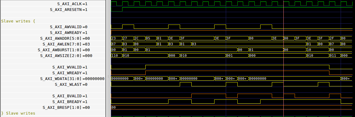
For now, let’s turn our attention to the write channel. A basic AXI write transaction looks like Fig. 9 on the right.
 |
There are four important sections of logic in this figure. First, when the
design is idle we’ll want AWREADY to be high. That way we won’t need to wait
an extra cycle after AWVALID goes high before AWREADY & AWVALID are high
together like Xilinx’s design
did. Second, there’s the
write address transaction, where AWVALID & AWREADY. Third, there’s a series
of “beats” where WVALID is true and valid data are sent across the channel.
Finally, BVALID is set to true on the clock cycle after
WVALID & WREADY & WLAST.
You may notice from Fig. 9 that I’ve kept the WREADY line low until after
AWVALID & AWREADY. That just simplified the design below. If I need to
press for lower latency later, I may need to come back and adjust this later.
If you were to place these states into an initial FSM, you might get something looking like Fig. 10 below.
 |
In this figure, you can see all of the four stages of the transaction we just discussed above. Sadly, however, this FSM, diagram is far from complete.
Let’s work through some of the problems. First, my entire goal was
throughput. Fig. 9 illustrates a transaction that takes N+2 clock periods,
and our state machine in Fig. 10 doesn’t allow back to back transactions. So
let’s start adding some more states and transitions.
- In order to avoid stalls, we’ll need to make sure to raise
AWREADYon the same clock thatWVALID & WLASTis true. Worse, in order to register everything, we’ll need to setAWREADYon the clock beforeWVALID & WLASTare true.
 |
What should we do, though, if AWREADY & WREADY & !WVALID?
To solve this problem, I chose to use a skid buffer. The skid buffer, shown in Fig. 11 on the left, will take a registered interface and produce a combinatorial interface.
-
That still leaves us with the condition where we’ll need to transition from
AWVALID & WVALID & WLASTtoWVALID & WREADY & BVALID(and possiblyWLAST). This will require two more states, one forWREADY & BVALIDand another forWREADY & WLAST & BVALID.This last state, however, gives us another problem. What happens when
WVALID & !BREADY? In that case, we’ll need to store our new response in a skid buffer, dropAWREADY, and wait forBREADY.
I then tried to diagram out this state machine for you, to help you understand all the various parts and pieces of such a transaction. What I came up with was Fig. 12 below.
 |
Sadly, it’s not very understandable, much less complete. Even worse, this state diagram wasn’t helping me. Instead, I gave up in frustration. There are just too many states and transitions to make this understandable, much less correct.
It’s certainly not simple enough to understand from examination.
So, let me let you in on a secret: I didn’t use a state diagram to build this core.
What?? Why not?
Because, in my mind, this core was never an FSM. It didn’t have the typical FSM structure. In my mind, it was always a series of pipeline stages, together with the logic necessary to handle the transitions from one stage to the next. As I designed this core, I envisioned three write stages, separated by a clock, as shown in Fig. 13 below.
 |
The first stage was the AW* stage where the AW* signals would (or wouldn’t)
be valid. In Fig. 13, you can see how this stage will either take a clock
cycle or not, as provided by the
skid buffer.
The second stage was the
WREADY stage, ending in the r_bvalid internal
skid buffer.
Timing was driven by this write-data stage, and no more than one request was
ever allowed to be within it. Once WVALID & WLAST were true, the response
would either go into the
skid buffer,
called r_bvalid in Fig. 13, or directly to the BVALID output stage.
Further, a request could always be accepted any time:
-
If both
WREADYandr_bvalidstages were empty, a request could always be accepted. -
Otherwise, accepting a request required several other conditions to be true together:
a. Either
BVALIDwas false, orBREADYwas true, indicating that nothing was blocking at the final stage, and …b. If something was in the
S_AXI_WREADYstage, versus in ther_bvalidskid buffer, thenWVALID && WLASTmust both be before accepting a new request.Note that, in this design,
r_bvalidwill never be true unlessBVALIDis also true. This is a common skid buffer, property, but we can still use a formal assertion if we aren’t confident this will be true.
So, instead of using the
FSM
in Fig. 12 that left me more confused, I chose
to focus instead on a signal trace diagram to understand what needed to be
done. My goal, as you recall, was to pack all of these parts and pieces
of a write transaction together as tightly as possible, so that
this core
could
support WVALID being true without interruption across multiple bursts. The
result should look something like Fig. 14 on the left.
 |
Building this
design
required two tricks. The first we’ve already discussed,
and that’s the two skid
buffers–both on the
AW* request side and again on the BVALID side.
The second trick, which has already separated our approach today from many
other approaches to building an AXI
slave, is that we’ve chosen to use the various output signals in place of
any separate FSM
state. This will keep us from making the same mistakes Xilinx
made, when their logic
checked for AxVALID & AxREADY & something_else.
Above all else, we’re going to lean very heavily on the formal AXI properties to convince ourselves that this works.
The Skid Buffers
The key to high throughput when using the AXI bus is really the skid buffers. If you are going to do anything with AXI, whether the full AXI standard, AXI-lite, or even AXI stream, you need to understand skid buffers.
Why are skid buffers so important? Because unlike Wishbone, AXI output signals must not depend upon any combinatorial paths from the inputs according to the specification. This is great for maintaining high speed signaling when using high fanout signals, but it becomes a challenge for the designer and they can be an ugly challenge as well for the engineer who wants to verify his design with induction.
I’ve now discussed skid buffers on this blog several times. First, under the name of “double buffers” when discussing pipeline strategies, and then again when we discussed building a functioning AXI-lite slave. More recently, I devoted a whole article to the topic. Eric LaForest also has posted a wonderful article describing them under the name “skid buffers”.
For these reasons, I won’t discuss skid buffers further here, but I will encourage you to go back and examine one or more of these articles before reading further.
The write channel
Are you ready to dive into the code?
The first thing I do when building something to process
AXI
signals is to rename the parameters
Xilinx provides. This isn’t because I dislike their
naming convention, on the contrary, I like it: with the exception of the _S_
their convention is quite descriptive. I understand therefore that
C_S_AXI_ADDR_WIDTH is the number of address bits associated with the
AXI
slave port to my design. It’s just that using this long identifier means
that either I need to extend the width of my text editor and thus lose the
monitor size gains of the last decade, or I need to abbreviate these values.
Here are my chosen abbreviations: AW for address width, DW for data width,
and IW for transaction ID width.
	localparam	AW = C_S_AXI_ADDR_WIDTH;
	localparam	DW = C_S_AXI_DATA_WIDTH;
	localparam	IW = C_S_AXI_ID_WIDTH;
	localparam	LSB = $clog2(C_S_AXI_DATA_WIDTH)-3;
These shorthand parameters are defined as localparams, so Vivado
should still be able to recognize this file.
Further, you may remember that
AXI addresses
are not like
WB addresses. In
AXI,
the address doesn’t reference a word of memory, but rather an octet
of memory. This means
that there will almost always be some number of low order address bits that
aren’t really necessary to any word-level transaction. This is the purpose
of the LSB short-hand above. When we send our address
to our downstream non-AXI port, we’ll only send the [AW-1:LSB] bits to
simplify the processing there. Sub-word handling by the external slave
will be done using the o_wstrb signals.
The next step is to handle the incoming write address
skid buffer.
I’m going to use the m_aw prefix to reference the values coming out of
and going into this skid
buffer. The S_AXI_AW*
signals going into the skid
buffer will maintain
their names, and denote a separate stage of processing.
	////////////////////////////////////////////////////////////////////////
	//
	// Skid buffer
	//
	// ...
	//
	skidbuffer #(.DW(AW+2+3+8+IW))
		awbuf(S_AXI_ACLK, !S_AXI_ARESETN,
		S_AXI_AWVALID, S_AXI_AWREADY,
			{ S_AXI_AWADDR, S_AXI_AWBURST, S_AXI_AWSIZE,
					S_AXI_AWLEN, S_AXI_AWID },
		m_awvalid, m_awready,
			{ m_awaddr, m_awburst, m_awsize, m_awlen, m_awid });
These m_aw* signals are the equivalent of their S_AXI_AW* counterparts,
with the exception being that m_awready is combinatorially determined.
Similarly, there’s combinatorial logic within the
skid buffer
to generate the other m_aw* signals. That way this
skid buffer
won’t cost us any clock delays.
The next piece of logic is, in many ways, the key to understanding the write logic. This is where we’ll control the ready lines for both the write address and the write data channel.
As mentioned above, we’ll idle with AWREADY high and WREADY low.
	initial	axi_awready = 1;
	initial	axi_wready  = 0;
	always @(posedge S_AXI_ACLK)
	if (!S_AXI_ARESETN)
	begin
		axi_awready  <= 1;
		axi_wready   <= 0;
Following Xilinx’s convention, I’m using the axi_* as a prefix to
describe registered values that will then drive the outgoing S_AXI_*
signals. The exception to this rule is axi_awready.
axi_awready will be the registered component of the ready signal,
m_awready, going into the combinatorial side of the
skid buffer
above. Therefore, imagine, as you go through this, that we are setting
m_awready anytime we set axi_awready, but remember that we may also
override this registered value to set m_awready high when accepting
subsequent packed bursts across the channel.
From there, the basic starting logic is simple: once m_awvalid and m_awready
are true, move to the write data stage of our burst processor. That means
we’ll drop axi_awready until the the packet clears the S_AXI_WREADY stage.
	end else if (m_awvalid && m_awready)
	begin
		axi_awready <= 0;
		axi_wready  <= 1;
Do you remember the post about the most common AXI
mistake?
It’s a common mistake
to check for anything other than *valid and *ready at the step above.
Were we to do that, we might miss and therefore drop an incoming request.
Next, axi_awready is set so we can accept another packet if this is the
last data value in the burst and if there’s an open position in our outgoing
skid buffer.
We don’t need to check for two positions, just one. However,
WVALID & WREADY & WLAST will consume one of the two positions.
Similarly, we’ll drop axi_wready and leave this processing stage once we
the last data value is accepted.
This gets a bit more interesting, though, in the next step. The if below
only looks like it is checking for S_AXI_WVALID & S_AXI_WREADY. Remember,
this is the second if in a cascaded if block. Therefore, we are now
checking S_AXI_WVALID && S_AXI_WREADY and
!m_awvalid || !m_awready. How is this not violating the basic rule of AXI
handshaking?
	end else if (S_AXI_WVALID && S_AXI_WREADY)
	begin
		axi_awready <= (S_AXI_WLAST)&&(!S_AXI_BVALID || S_AXI_BREADY);
		axi_wready  <= (!S_AXI_WLAST);
Originally, when I wrote this code, it didn’t violate the rule because I
guaranteed that S_AXI_AWREADY would be false during the data stage of this
transaction. That was arranged by the code above. This worked well, but it
cost me a clock of throughput on every burst.
Now, and we’ll get to this in a moment, there’s the possibility that
m_awready might be true when S_AXI_WVALID && S_AXI_WREADY. In particular,
it may be true when WVALID & WREADY & WLAST, and so we’d be ready at that
time to accept another burst. Hence, I’m not violating the rule, rather
I’m combining two possibilities in the first part of this cascaded if.
We can now move on to the rest of this key logic block. At this point, though,
most of the critical work has been done. All that’s left is to make
cerain that axi_awready, once lowered to deal with the write data, is
properly raised again once done.
	end else if (!axi_awready)
	begin
		if (S_AXI_WREADY)
			axi_awready <= 1'b0;
		else if (r_bvalid && !S_AXI_BREADY)
			axi_awready <= 1'b0;
Specifically, we’ll want to keep axi_awready clear as long as we are in the
write data stage (the S_AXI_WREADY stage) of our processing or if the
outgoing skid buffer
is full, i.e. r_bvalid is true. r_bvalid will only be true, however, if
then the outgoing skid
buffer is stalled.
Remember, if the outgoing
skid buffer
is full, that is if the internal buffer within it has valid data within it,
then the S_AXI_BVALID signal at the output must also be true, so we
don’t need to check for it here.
In all other cases, we’ll clear the stall condition so we can accept another write address request.
		else
			axi_awready <= 1'b1;
	end
We’ll also need to copy and cache the values we’ll need to calculate
subsequent write
addresses within
the burst: the burst type, virtual bus width, wsize, and the burst length.
	always @(posedge S_AXI_ACLK)
	if (m_awready)
	begin
		waddr    <= m_awaddr;
		wburst   <= m_awburst;
		wsize    <= m_awsize;
		wlen     <= m_awlen;
	end else if (S_AXI_WVALID)
		waddr <= next_wr_addr;
In this logic, next_wr_addr is created by applying our
AXI address logic to the current write address
to get the next address.
The write address
calculation
itself now becomes really simple, given the axi_addr
module we built earlier.
On m_awvalid & m_awready, we set waddr according to the incoming address.
Then, on every accepted write value, it gets set to next_wr_addr above.
All that’s left is to call axi_addr to get that next write address.
	axi_addr #(.AW(AW), .DW(DW))
		get_next_wr_addr(waddr, wsize, wburst, wlen,
			next_wr_addr);
Before we move on to the
skid buffer
for the return channel, let’s not forget to write this
AXI data to our external slave interface.
The neat thing about this is that, by this point in our processing,
this last bit is easy. We can just set these outputs to the
AXI inputs and our registered address,
waddr, and use one little piece of combinatorial logic, WVALID & WREADY,
to indicate that it is time to write.
This should give our external AXI-unaware slave component plenty of slack to actually process this request. Indeed, by this point, we’ve removed all of the AXI complexity from what this external core needs to process.
	always @(*)
	begin
		o_we = (S_AXI_WVALID && S_AXI_WREADY);
		o_waddr = waddr[AW-1:LSB];
		o_wdata = S_AXI_WDATA;
		o_wstrb = S_AXI_WSTRB;
	end
It’s now time to start looking at the skid buffer for the return response.
Unlike the earlier
skid buffer,
I share the r_bid signal with the S_AXI_WREADY stage, which forces this
skid buffer,
to have a bit of a different structure–enough so that I’ve written this
write return skid buffer
into the module’s logic rather than referencing a submodule.
The critical part of this
skid buffer
is the valid signal, indicating whether or not something is within it.
In this case, we’re calling this signal r_bvalid.
As might be expected, r_bvalid is cleared on any reset.
	initial	r_bvalid = 0;
	always @(posedge S_AXI_ACLK)
	if (!S_AXI_ARESETN)
		r_bvalid <= 1'b0;
r_bvalid is set, however, if two conditions are true, as shown in
Fig. 13 above. To follow, consider that any time
WVALID & WREADY & WLAST we want to set the outgoing BVALID. The only time
when we cannot set BVALID is if BVALID is already set, but BREADY is
clear (indicating a stall condition). In that case, we still need to note
that we are ready for a second response somewhere else–i.e. in the
skid buffer. Hence, the
skid buffer
is only activated any time a value would be placed into the outgoing
position, but when the outgoing position is already full and stalled..
	else if (S_AXI_WVALID && S_AXI_WREADY && S_AXI_WLAST
			&&(S_AXI_BVALID && !S_AXI_BREADY))
		r_bvalid <= 1'b1;
Once the stall is clear, the contents of the
skid buffer.
will always move forward to the outgoing position, so we can then clear the
internal valid line, r_bvalid.
	else if (S_AXI_BREADY)
		r_bvalid <= 1'b0;
I broke the basic mold of the skid
buffer
with the transaction ID. We need to record the transaction ID anytime
m_awvalid & m_awready are both true. Since we are guaranteeing that there
will always be a place for any accepted write transaction in either the
skid buffer at the end
or the return response position, we can then just copy the ID from m_awid
to the skid buffer’s
data store. If the skid
buffer
isn’t valid yet, its data is at least still allocated as part of our scheme
to keep from needing to drop WREADY mid-transaction.
	always @(posedge S_AXI_ACLK)
	begin
		if (m_awready)
			r_bid    <= m_awid;
We can even simplify this somewhat by only checking m_awready instead of both
m_awready and m_awvalid.
Next, anytime the return transaction position is idle we can forward this
transaction identifier to our return register, axi_bid.
		if (!S_AXI_BVALID || S_AXI_BREADY)
			axi_bid <= r_bid;
	end
This is one of those cases where the logic cannot be simplified further.
(I know, I tried.) What we want is to forward to the outgoing response
position any time !(S_AXI_BVALID && !S_AXI_BREADY). If we only check for
S_AXI_BREADY, however, the bus master isn’t required to keep this ready
while waiting for a response. We might find that BID then never gets set
properly.
You may also note that this handling of the ID requires a minimum of two
three clock periods. On the first clock, m_awvalid & m_awready will be
true qualifying m_awid. On the second clock period, r_bid will contain
the current transaction ID. This is also the earliest
period where WREADY will be true for this transaction. It may also be
the last period of the transaction, were WVALID & WLAST to be true as well.
Then, on the third clock period, axi_bid would contain the correct
write burst identifier.
Now that we have the
skid buffer
in please, we can discuss the return BVALID signal.
	initial	axi_bvalid = 0;
	always @(posedge S_AXI_ACLK)
	if (!S_AXI_ARESETN)
		axi_bvalid <= 0;
We’ll want to set this signal true any time WVALID & WREADY & WLAST.
If BVALID were already true, then setting it again–even if the
channel were stalled–won’t hurt.
	else if (S_AXI_WVALID && S_AXI_WREADY && S_AXI_WLAST)
		axi_bvalid <= 1;
Otherwise, any time S_AXI_BREADY is true, we can move the
skid buffer
valid signal, r_bvalid, into the output position.
	else if (S_AXI_BREADY)
		axi_bvalid <= r_bvalid;
That leaves one big piece of write logic we haven’t yet addressed, m_awready.
As I mentioned above, this piece of logic is built combinatorially off of
the axi_awready register.
	always @(*)
	begin
		m_awready = axi_awready;
The one piece of combinatorial logic is required in order to be able to accept a new write address on the last clock cycle of the write data–especially because we can only do so if there is, or is about to be, an open position in the outgoing skid buffer.
First, we know that if WREADY is true, then there’s at least one position
in the skid buffer–the
one for the write data once it completes. That was
one of the design rules we’ve chosen–one I tried to illustrate in Fig. 13
above.
We’ll now need to make certain, if we set the ready line for the write address
channel, that a second output position is also available. Since our outgoing
buffer only holds only one position and that’s already taken,
the final outgoing BVALID position must be clear or clearing in order to
accept a new transaction. Hence, we’ll need to check that the
current write transaction can fit in the S_AXI_BVALID output stage on the
next cycle.
		if (S_AXI_WVALID && S_AXI_WREADY && S_AXI_WLAST
			&& (!S_AXI_BVALID || S_AXI_BREADY))
			m_awready = 1;
	end
All that’s left of the write channel side is to clean up. Specifically,
following Xilinx’s convention, we’ve set register values axi_* but the
actual I/O values are named S_AXI_*. We’ll need to copy our values to
the actual I/O ones.
	assign	S_AXI_WREADY  = axi_wready;
	assign	S_AXI_BVALID  = axi_bvalid;
	assign	S_AXI_BID     = axi_bid;
We also need to set the BRESP return code.
AXI offers four return code possibilities: OKAY, EXOKAY, SLVERR, and DECERR. Since this simple slave doesn’t produce any errors, neither SLVERR nor DECERR make sense to return. EXOKAY is only allowed if this slave supports exclusive access, which we don’t.
The AXI
exclusive access protocol is rather complex. It involves a first
request to read a value with ARLOCK set. If the slave responds with EXOKAY,
the slave then needs to record the
address details
of the transaction. If
at some time later, the same register is written to with AWLOCK high and
no intervening writes, then the slave may return EXOKAY and adjust the
register. If the slave returns OKAY instead, the register is not allowed to
be modified.
Since we aren’t supporting this exclusive access portion of the protocol,
we’ll set the BRESP to 2'b00 to indicate an OKAY response. I may need
to come back and add exclusive access support later, but that will be as part
of a separate blog article.
Therefore, since this doesn’t produce any bus errors, nor does it support exclusive access, 2’b00 will always be the correct response.
assign S_AXI_BRESP = 0;That’s the write channel, and a high speed one at that! Remember, we managed to get 100% throughput (one write burst per clock) once fully loaded. That’s a bit of performance Xilinx’s demo code never achieved.
If this is performance you want in your design, you can find this AXI slave core here.
The Read Channel
Our basic approach to handling any read request will be to aggressively
read any time and as often as we can, pushing as much logic to the left
in this operation as we can. That also means we’ll issue a slave read
request on the same clock that S_AXI_ARVALID is true.
We’ll start with axi_arready. As with the write address ready, this one
also idles high.
	initial axi_arready = 1;
	always @(posedge S_AXI_ACLK)
	if (!S_AXI_ARESETN)
		axi_arready <= 1;
Then on any request, we’ll drop ARREADY.
	else if (S_AXI_ARVALID && S_AXI_ARREADY)
		axi_arready <= 0;
Well, not quite. If we did that, then we would require a minimum of two
clocks for every one-burst read: One clock for ARVALID & ARREADY and a second
where !ARREADY. This would prevent us from being able to do back-to-back
reads for short bursts.
So let’s adjust this so that on any read address request, we drop ARREADY
if and only if o_rd, our outgoing sub-slave read signal, is also true.
This sub-slave read signal is a combinatorial signal that will only be true
if the outgoing read data channel isn’t stalled. To support burst
transactions, we’ll need to only let ARREADY stay high if the burst
length is one, or equivalently if ARLEN==0. Remember, in
AXI,
the burst length is always one more than AxLEN, so we’ll go high
immediately on any single item burst request where o_rd is also high.
	else if (S_AXI_ARVALID && S_AXI_ARREADY)
		axi_arready <= (S_AXI_ARLEN==0)&&(o_rd);
Finally, any time the output channel is not stalled, we can check whether we are about to place the last value.
	else if (!S_AXI_RVALID || S_AXI_RREADY)
	begin
		if ((!axi_arready)&&(S_AXI_RVALID))
			axi_arready <= (axi_rlen <= 2);
	end
This really doesn’t make much sense without knowing what axi_rlen is.
axi_rlen is the name of a counter I’m using to store the number of items
currently remaining in this burst. It is initially set to AXI_ARLEN+1.
Ever after, on any read, axi_rlen is decremented. Once axi_rlen reaches
zero, the read is complete and AXI_RVALID should be low.
That’s why we can check for axi_rlen == 2 above. If axi_rlen == 2, then
on the next cycle, axi_rlen will be one and RLAST will then be set. We
then need to be able to accept a new read request, as shown in Fig. 7 above,
or we won’t be able to continue our high speed transaction.
Here’s what the logic for axi_rlen looks like. Because we are using this
to know our position in a read burst, it must idle at zero. That way
axi_rlen == 0 can also be used as an indication that we are no longer within
a burst.
	initial	axi_rlen = 0;
	always @(posedge S_AXI_ACLK)
	if (!S_AXI_ARESETN)
		axi_rlen <= 0;
On any read request, we’ll set axi_rlen to the number of items remaining to
be returned, or S_AXI_ARLEN+1.
	else if (S_AXI_ARVALID && S_AXI_ARREADY)
		axi_rlen <= (S_AXI_ARLEN+1);
Well, that’s the basic idea. That’s not quite it though. The problem is
that, if there’s already an item stalled in the return channel path, then
we still need to return that item too. We’ll
therefore merge that last value, the one that is waiting for S_AXI_RREADY,
into our “to-be-returned” axi_rlen counter.
	else if (S_AXI_ARVALID && S_AXI_ARREADY)
		axi_rlen <= (S_AXI_ARLEN+1)
				+ ((S_AXI_RVALID && !S_AXI_RREADY) ? 1:0);
This works because the value that’s stalled in the return position has already been read. It won’t get updated by this new read address request.
Any time a read value is returned, we’ll then simply decrement our counter.
	else if (S_AXI_RREADY && S_AXI_RVALID)
		axi_rlen <= axi_rlen - 1;
Notice that we didn’t check whether axi_rlen was greater than zero or not.
S_AXI_RVALID is equivalent to axi_rlen > 0, and a basic assertion (below)
proves that to be the case. Hence we only need to check S_AXI_RVALID.
How about our read address?
This one’s a little tricky. Because we stuffed our first read operation into
the same clock cycle as ARVALID & ARREADY, the
address
we record needs to be not the address given, but rather the
next address–assuming
we read on the same cycle. This also means that the values we feed to our
axi_addr next-address
module will need to
depend upon whether the read address is sourced from
ARADDR or raddr below.
	// Calculate the next read address
	always @(posedge S_AXI_ACLK)
	if (o_rd)
		raddr <= next_rd_addr;
	else if (S_AXI_ARREADY)
		raddr <= S_AXI_ARADDR;
Actually calculating the next address requires registering and keeping track of several values from the AXI address packet: the burst type, the transfer size per beat, and the total number of beats. While we’re at it, we’ll copy the read ID as well.
	always @(posedge S_AXI_ACLK)
	if (S_AXI_ARREADY)
	begin
		rburst   <= S_AXI_ARBURST;
		rsize    <= S_AXI_ARSIZE;
		rlen     <= S_AXI_ARLEN;
		rid      <= S_AXI_ARID;
	end
Once we have all these values, we can then calculate the next read address.
	axi_addr #(.AW(AW), .DW(DW))
		get_next_rd_addr((S_AXI_ARREADY ? S_AXI_ARADDR : raddr),
				(S_AXI_ARREADY  ? S_AXI_ARSIZE : rsize),
				(S_AXI_ARBURST  ? S_AXI_ARBURST: rburst),
				(S_AXI_ARLEN    ? S_AXI_ARLEN  : rlen),
				next_rd_addr);
This may be one of the more delicate parts of this operation. A quick yosys check,
% yosys -p 'read -sv axi_addr; synth_xilinx; show'reveals an image showing that the logic is four levels deep. Adding this address check, therefore, might make it difficult to meet timing. That means that I might need to revisit this step later if/when I ever run into timing problems here.
By the way, if you’ve never tried the
yosys show command,
it can be very instructive to see and learn how
yosys
is choosing to synthesize your code.
But I digress.
Now that we know
the address,
we’re able to drive the read ports of our (simplified) external slave. These
include o_rd, the flag that indicates when to read, and
o_raddr to indicate the address to read from.
We’ll want to read on the same clock as any incoming request, or equivalently
any time ARREADY is false, indicating that we are still working through
the middle of a burst.
	always @(*)
	begin
		o_rd = (S_AXI_ARVALID || !S_AXI_ARREADY);
However, if the read return channel is ever stalled, such as when
!S_AXI_RVALID || S_AXI_RREADY then we cannot perform our read lest
we cause our outgoing data to change before it has been accepted.
		if (S_AXI_RVALID && !S_AXI_RREADY)
			o_rd = 0;
We’ve also discussed generating the read address above. On any given clock
cycle, this address will be given by raddr if we are in the middle of a
burst, such as when !S_AXI_ARREADY, and then by S_AXI_ARADDR on the first
beat of any burst. We can use S_AXI_ARREADY to tell the difference between
these two choices.
		o_raddr = (S_AXI_ARREADY ? S_AXI_ARADDR[AW-1:LSB] : raddr[AW-1:LSB]);
	end
Notice also that we’ve used LSB above to drop the subword addressing.
I’ve done this for the simple reason that I don’t have any modules that
would use the subword address.
That gets us past accepting the read request from the address channel, storing the details of that request and updating those details from one beat to the next. We’ve also issued the read request from our external peripheral. We just haven’t set the read output return values yet.
Let’s do that now.
Typically, the most difficult part of any of these channels is either the valid or the ready signal–whichever one you have control over, whether master or slave. These signals are just the type of signals that you can’t afford to mess up. If you mess up the data, the bus will still work. If you mess up the response, your program might fail but the bus won’t lock up. On the other hand, if you mess up the valid/ready signals, the return ID signal, or even the last signal, you might well lock everything up hard.
So let’s keep this simple.
	initial	axi_rvalid = 0;
	always @(posedge S_AXI_ACLK)
	if (!S_AXI_ARESETN)
		axi_rvalid <= 0;
Any time we read from memory, we’ll set the outgoing valid signal.
	else if (o_rd)
		axi_rvalid <= 1;
Keep in mind, this isn’t quite as simple as it looks since we’ve already put
a some combinatorial logic into the o_rd signal. One of the critical pieces
of logic there is the piece that forces o_rd to be zero any time the bus is
stalled.
Next, if o_rd is low, then we can clear the return valid signal any time
S_AXI_RREADY is true.
	else if (S_AXI_RREADY)
		axi_rvalid <= 0;
Let’s now turn our attention to the return ID signal next. This particular signal can only change if the return channel isn’t stalled.
	always @(posedge S_AXI_ACLK)
	if (!S_AXI_RVALID || S_AXI_RREADY)
	begin
In that case, the new ID can either be the ID from a newly accepted burst,
		if (S_AXI_ARVALID && S_AXI_ARREADY)
			axi_rid <= S_AXI_ARID;
or alternatively the ID we saved in our buffer when the new burst was accepted.
		else
			axi_rid <= rid;
	end
In many ways, the RLAST signal uses the same logic as the return ID. As
with the ID signal, it cannot change if the return channel is stalled.
	initial axi_rlast   = 0;
	always @(posedge S_AXI_ACLK)
	if (!S_AXI_RVALID || S_AXI_RREADY)
	begin
The return channel will be stalled anytime RVALID && !RREADY. The
above expression is just this stall logic negated according to De Morgen’s
laws.
If the return channel is not stalled, then we have a couple of cases to deal
with. The first is if we just accepted a request, indicated by
ARVALID & ARREADY. In that case, we’ll set axi_rlast if the burst
only had a single beat to it.
		if (S_AXI_ARVALID && S_AXI_ARREADY)
			axi_rlast <= (S_AXI_ARLEN == 0);
Otherwise we need to set axi_rlast so that axi_rlast == (axi_rlen == 1).
Ideally, we’d just set axi_rlast <= (axi_rlen == 1) but this ignores the
possibility of axi_rlen changing on this clock as well due to a return
value being accepted. Hence, we set axi_rlast if axi_rlen is about
to become one, or if the interface is stalled then we simply set it based
upon the current value of axi_rlen.
		else if (S_AXI_RVALID)
			axi_rlast <= (axi_rlen == 2);
		else
			axi_rlast <= (axi_rlen == 1);
	end
As for setting RDATA, the external sub-slave did that for us. Remember
how we insisted that it have the following read logic?
always @(posedge S_AXI_ACLK)
if (i_rd)
	o_rdata <= mem[i_raddr];
Notice here that the i_rd signal is key! This allows us to just set the
RDATA output combinatorially based upon this i_rdata input.
	always @(*)
		axi_rdata = i_rdata;
If the slave were to set o_rdata on any other criteria, then it might
possibly change RDATA while the output channel was stalled, as indicated
by S_AXI_RVALID & S_AXI_RREADY. This would be a protocol violation, so it
is important that the slave only set RDATA whenever the o_rd is also
true.
The rest of the design simply involves setting our various output signals to their internally registered counterparts.
	//
	assign	S_AXI_ARREADY = axi_arready;
	assign	S_AXI_RVALID  = axi_rvalid;
	assign	S_AXI_RID     = axi_rid;
	assign	S_AXI_RDATA   = axi_rdata;
	assign	S_AXI_RRESP   = 0;
	assign	S_AXI_RLAST   = axi_rlast;
	//
That’s all it takes to create a high throughput AXI slave design. Feel free to check it out here.
Well, yes, but the key question is, does it work? We’ve already seen that there were both several bugs in Xilinx’s design, as well as noting that it couldn’t handle any significant throughput. How can we be sure that this design is any better?
For that we’ll turn to formal verification.
Formal Verification
The majority of the formal verification work we need will be done by a formal property checker. That will make a lot of this verification work easy.
`ifdef	FORMAL
	// ...
	faxi_slave	#(
		.F_AXI_MAXSTALL(6),
		.C_AXI_ID_WIDTH(C_S_AXI_ID_WIDTH),
		.C_AXI_DATA_WIDTH(C_S_AXI_DATA_WIDTH),
		.C_AXI_ADDR_WIDTH(C_S_AXI_ADDR_WIDTH),
		.F_LGDEPTH(F_LGDEPTH))
		f_slave(
		.i_clk(S_AXI_ACLK),
		.i_axi_reset_n(S_AXI_ARESETN),
		//
		// Address write channel
		//
		.i_axi_awvalid(m_awvalid),
		.i_axi_awready(m_awready),
		.i_axi_awid(   m_awid),
		.i_axi_awaddr( m_awaddr),
		.i_axi_awlen(  m_awlen),
		.i_axi_awsize( m_awsize),
		.i_axi_awburst(m_awburst),
		.i_axi_awlock( 1'b0),
		.i_axi_awcache(4'h0),
		.i_axi_awprot( 3'h0),
		.i_axi_awqos(  4'h0),
	//
	//
		//
		// Write Data Channel
		//
		// Write Data
		.i_axi_wdata(S_AXI_WDATA),
		.i_axi_wstrb(S_AXI_WSTRB),
		.i_axi_wlast(S_AXI_WLAST),
		.i_axi_wvalid(S_AXI_WVALID),
		.i_axi_wready(S_AXI_WREADY),
	//
	//
		// Response ID tag. This signal is the ID tag of the
		// write response.
		.i_axi_bvalid(S_AXI_BVALID),
		.i_axi_bready(S_AXI_BREADY),
		.i_axi_bid(   S_AXI_BID),
		.i_axi_bresp( S_AXI_BRESP),
	//
	//
		//
		// Read address channel
		//
		.i_axi_arvalid(S_AXI_ARVALID),
		.i_axi_arready(S_AXI_ARREADY),
		.i_axi_arid(   S_AXI_ARID),
		.i_axi_araddr( S_AXI_ARADDR),
		.i_axi_arlen(  S_AXI_ARLEN),
		.i_axi_arsize( S_AXI_ARSIZE),
		.i_axi_arburst(S_AXI_ARBURST),
		.i_axi_arlock( S_AXI_ARLOCK),
		.i_axi_arcache(S_AXI_ARCACHE),
		.i_axi_arprot( S_AXI_ARPROT),
		.i_axi_arqos(  S_AXI_ARQOS),
	//
	//
		//
		// Read data return channel
		//
		.i_axi_rvalid(S_AXI_RVALID),
		.i_axi_rready(S_AXI_RREADY),
		.i_axi_rid(S_AXI_RID),
		.i_axi_rdata(S_AXI_RDATA),
		.i_axi_rresp(S_AXI_RRESP),
		.i_axi_rlast(S_AXI_RLAST),
		//
		// Formal outputs
		//
		.f_axi_awr_nbursts(f_axi_awr_nbursts),
		// ...
		.f_axi_rd_nbursts(f_axi_rd_nbursts),
		.f_axi_rd_outstanding(f_axi_rd_outstanding),
		//
		// ...
		.f_axi_wr_addr(f_axi_wr_addr)
		// ...
	);
Including the property file by itself is usually enough to find errors within the design. Indeed, just adding the property file alone to someone else’s core, with whatever strange logic within it that I’m not familiar with, has been all I’ve done to find most of the errors I’ve shared on twitter.
It’s not enough to prove that the design has no errors.
For that, we need to turn to induction. Further, when using induction, we need to add constraints to tie the state found within the formal property file to the state of our design.
The following are several examples of the properties I’ve used to do this.
We’ll start with the write side.
	////////////////////////////////////////////////////////////////////////
	//
	// Write induction properties
	//
	////////////////////////////////////////////////////////////////////////
	//
	//
The formal property file counts the number of outstanding address write requests. In the case of this design, there will never be more than two outstanding burst writes.
	always @(*)
		assert(f_axi_awr_nbursts <= 2);
Now let’s look at each of those three possibilities, whether zero, one, or two outstanding write bursts.
If there are two outstanding requests, then one of them must be in the
return position, S_AXI_BVALID.
	always @(*)
	if (f_axi_awr_nbursts == 2)
		assert(S_AXI_BVALID && (r_bvalid || S_AXI_WREADY));
On the other hand, if only one request is outstanding, then it must be in
either the return BVALID pipeline stage or in the WREADY accepting
data pipeline stage.
	else if (f_axi_awr_nbursts == 1)
		assert(S_AXI_BVALID ^ S_AXI_WREADY);
Finally, if nothing is outstanding on the write channel, then neither BVALID
nor WREADY should be true.
	else
		assert(!S_AXI_BVALID && !S_AXI_WREADY);
This same logic is then repeated to check burst IDs. We’ll skip that here and move on.
I mentioned above that any time a value was in the outgoing write
skid buffer,
that is any time r_bvalid was true, then BVALID must also be true.
Let’s double check that here.
	always @(*)
	if (r_bvalid)
		assert(S_AXI_BVALID);
We’ll also need to check the axi_awready signal. As you may recall, this
was the registered component of m_awready, the incoming
skid buffer
read signal. Specifically, we want to make absolute certain that we’ll
be ready to read any new write address any time there’s nothing in the
write data stage, where S_AXI_WREADY, or in the outgoing skid
buffer,
as marked by r_bvalid. Indeed, this property is so strong, it’s a two
sided implication that we’ll want to check both ways. For that reason,
I’m using an equality assertion to check it below.
	always @(*)
		assert(axi_awready == (!S_AXI_WREADY && !r_bvalid));
One of the neat parts of the AXI formal property set is that one of the outputs from it is the current write address. You can use this to double check your own address computation. We’ll do that here, and so double check that our outgoing address truly does match the address it should be.
	always @(*)
	if (S_AXI_WREADY)
	begin
		assert(f_axi_wr_addr  == waddr);
		// ...
	end
With that, we can now turn our attention to verifying the read side. As before, we’ll focus on those properties that are necessary to validate that this works when using induction, since the basic AXI formal properties will take care of the rest.
	////////////////////////////////////////////////////////////////////////
	//
	// Read induction properties
	//
	////////////////////////////////////////////////////////////////////////
	//
	//
As with the write half, there will never be more than two outstanding read requests when using this core. Within the formal property set, there’s a counter capturing the number of read bursts–just like the counter for writes above. Here, we’ll just double check that this number is never out of bounds with the logic above.
	always @(*)
		assert(f_axi_rd_nbursts <= 2);
Now we have to define what that means within our core. In this case, and
for this core, if the number of outstanding bursts is ever more than one,
then there must be a value in the output position waiting to be returned.
Not only that, it must be the last item from the previous burst. Further,
our ARREADY signal must be low because we’ll only end up in this situation
if the response path were stalled on the last cycle.
	always @(*)
	if (f_axi_rd_nbursts == 2)
		assert(S_AXI_RVALID && S_AXI_RLAST && !S_AXI_ARREADY);
Not only will the formal property set count the number of bursts that are
outstanding, it will count the total number of outstanding values that need
to be returned. This number should match the axi_rlen value within our core.
	always @(*)
		assert(axi_rlen == f_axi_rd_outstanding);
Since the external sub-slave core will never stall in this design, we also
know that RVALID must be true any time any request is outstanding.
	always @(*)
	if (f_axi_rd_nbursts > 0)
	begin
		assert(S_AXI_RVALID);
Similarly, if there’s anything outstanding, then either S_AXI_ARREADY is
low blocking any incoming requests, or S_AXI_RVALID & S_AXI_RLAST are high
indicating that we are on the last beat of the burst.
assert(!S_AXI_ARREADY || (S_AXI_RVALID && S_AXI_RLAST));Likewise, if nothing is outstanding, then we want to make certain that
S_AXI_ARREADY is set so that we’ll be ready for the next burst.
	end else
		assert(S_AXI_ARREADY);
The property set also provides for some return ID checking, which I’ll skip
here. There’s also a read address check, which we can use to make certain
that o_raddr is properly set. That check requires tracking the address
from o_raddr to the return position where it would be checked.
Instead of working through those two tests, and for the sake of keeping things
short, I’d like to share one final read property. Specifically, any time
S_AXI_RLAST becomes true, that is if S_AXI_RLAST & !$past(S_AXI_RLAST),
then we want S_AXI_ARREADY to be high as well. We can use $rose() for
this purpose to check this transition.
	always @(posedge S_AXI_ACLK)
	if (f_past_valid && $rose(S_AXI_RLAST))
		assert(S_AXI_ARREADY);
While I initially wanted to check for more than that, such as when
S_AXI_ARREADY is false when S_AXI_RLAST is true, that much has
already been captured above.
Finally, we need one basic assumption, beyond those provided by the AXI property set.
	////////////////////////////////////////////////////////////////////////
	//
	// Assumptions necessary to pass a formal check
	//
	////////////////////////////////////////////////////////////////////////
	//
	//
We need to assume that the external sub-slave will behave properly. That is, it won’t change its value unless we’ve requested a read from it.
	always @(posedge S_AXI_ACLK)
	if (S_AXI_RVALID && !$past(o_rd))
		assume($stable(i_rdata));
`endif
endmodule
` That should give you a basic, yet brief, overview of the formal proof.
Cover
Normally I spend a section discussing cover properties. In this case, we’ve discussed one such cover property above. I figured it was important to point out that SymbiYosys generated a trace demonstrating that this cover point could be hit.
 |
GPIO
For some strange reason, it seems like I’m always fielding questions on whatever forum about the AXI-GPIO core provided by Vivado. In particular, there’s a lot of individuals complaining on-line about how slow this core is.
Consider for example, the trace shown in Fig. 16 below, drawn from a cover()
property placed external to the GPIO
core.
 |
Now, consider this: if all you did was connect your own basic I/O core to the output of this core, you could create your own GPIO controller running six times faster than this one. Even better, your new GPIO controller could then even handle both reads and writes at the same time. That’s not all. If you used this core, you wouldn’t need to waste more clocks going through Xilinx’s AXI to AXI-lite bridge.
That is, it would be 6x+ faster if only Xilinx’s interconnect supported such a speed. We’ll save that discussion for another day. Until then, it’s worth knowing that faster AXI interconnects exist.
Conclusions
We’ve just worked through a basic AXI slave core. Not only that, this slave core has the performance I’d expect from a high quality product–up to 100% sustained throughput.
Sadly, very few of the AXI slave cores I’ve examined can handle this kind of throughput. It’s a shame, too, since most people purchase FPGAs in order to get high speed performance for their own special application–whatever it is. On the other hand, if the logic you use within your FPGA is going to cripple your performance, then why purchase such an expensive component or go through the pain of digital design?
Perhaps the difference is the formal verification software, SymbiYosys as provided by SymbioticEDA. Because of the formal tool, and more specifically because of the formal AXI property file, I was able to build this design with confidence–even though I couldn’t figure out how to build a proper FSM state transition diagram for it.
Yes, formal methods truly make digital design a lot easier.
For wisdom is a defence, and money is a defence: but the excellency of knowledge is, that wisdom giveth life to them that have it. (Ecc 7:12)