
Want to use ZBasic? Let's have some fun--no actual FPGA required!
Now that you’ve seen the ZipCPU by itself, and now that you’ve built its tool chain, let’s look at together at what you can do with the ZipCPU as part of a larger design: ZBasic. Today, I’d like to show you how to run the ZBasic design within a Verilator-based simulation environment–one that simulates a QSPI flash, a serial port, and even (optionally) an SD-Card. If all goes well, we’ll run the ZipCPU’s CPU-Test program, and then even play 4x4x4 Tic-tac-toe.
But first, let’s start with a little history.
Why ZBasic?
When I first started out with the ZipCPU, my goal was to demonstrate it on a cheap hobbyist board. After my first development, on a Digilent Basys-3, I then built demonstrations for an Xess.com XuLA2-LX25 board, and then the Digilent CMod S6, the Arty, and most recently Nexys Video boards. You can still find most of these builds on-line in the XuLALX25SoC, S6SoC, OpenArty, and VideoZip repositories. Indeed, my main Github page still highlights the OpenArty project. Many of these boards are peripheral rich, and even for those that aren’t I purchased peripherals (mostly from Digilent) to have something fun and new to work with on each board. I have found it to be a fun exercise to learn how to build the RTL code to support a new peripheral and I would commend that exercise to every RTL student.
I then ran into the problem of supporting someone who didn’t have the peripherals I had. How could or should they use the ZipCPU, if their hardware didn’t match the hardware of one of the demonstration designs?
So, I backed up and took a look at all the designs I had. Almost all of them had some type of serial flash, some amount of block RAM, and a serial port. Why not then make a design that had only these peripherals?
That was, and still is, the purpose of the ZBasic design.
 |
Because the design
is intended to be generic, it has no
SDRAM,
nor any DDR3 SDRAM,
nor any other type of external RAM chip.
These interfaces tend to be board specific, and I wanted
this distribution to be as basic and as simple as possible. What that means,
though, is that the main
ZBasic
design requires 1MB of on-chip block RAM. Well, “requires” is a harsh word,
what I mean to say is that the design as currently configured on
github will try to infer 1MB of block RAM.
While few chips have this much RAM, it allows the
ZipCPU,
within the
ZBasic
design to have access to an abundance of RAM without worrying about the
interface to the RAM. Even better, this amount of RAM can be easily
changed using
AutoFPGA,
by changing only one number in the
AutoFPGA,
block RAM config
file
and then rebuilding the design (i.e. make autodata).
If that’s not enough, by just adding your own user code and
AutoFPGA
configuration file, you can add whatever additional hardware to the
ZBasic
distribution you want–SDRAMs included.
Okay, enough reminiscing, let’s discuss how to use the ZBasic design within a Verilator-based simulation.
Building ZBasic
Your first task in using the ZBasic design will be building the toolchain for the ZipCPU: binutils GCC and newlib. I’ll assume you’ve already done that, if not you’ll need to back up a step. I’m also going to assume that the toolchain is in your path, as we discussed when building it. The next step is to clone the ZBasic repository and build it. Since this repository doesn’t include a copy of GCC, it’s fairly light and a straightforward clone will work.
git clone https://github.com/ZipCPU/zbasic
cd zbasic
make
Voila! You have a ready built Verilator-based project ready to run! (Please create an issue on Github if you have problems, and this doesn’t work.)
Shall we run our first test? This test will require two windows, and a little bit of timing to do right. In your first window, go ahead an type the following–but don’t hit return on that last line yet or you might miss some of the simulation output. This will run the main simulation “test-bench” wrapper, and apply it to my (more modern) CPU test software–once you hit return (don’t do it yet).
cd sim/verilated
./main_tb ../../sw/board/cputest
In your second window, type the following–but don’t hit return. When you do (eventually) hit return, this will connect you to the running ZBasic simulation.
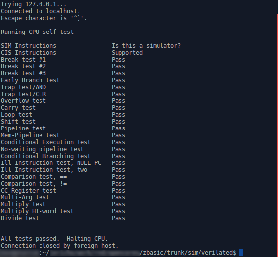
telnet localhost 8846Ok, now you can hit return in the first window and then the second. You should see the results of the CPU test, such as Fig 2 illustrates.
 |
If you had wanted, you could also turn on
VCD file
generation
by using the -d flag, and so trace every wire throughout the whole design as
it moves through this
CPU test.
./main_tb -d ../../sw/board/cputestBe aware, however, there’s a reason this option is turned off by default: your VCD file could easily top 11GB.
Alternatively, you could have just started the design on its own without giving a program to the ZipCPU. As the ZipCPU is configured within the ZBasic design, it starts up in a halted configuration. (This is optional–it can be configured to start immediately on power up–see the spec for more details.) If you give a program name as an argument, the simulation wrapper will load the program into memory and then clear the halt bit from the debugging interface. On the other hand, if you give the simulation driver no program name,
./main_tbthen you’ll need to load the ZipCPU’s program into memory–just as you would need to do on actual FPGA hardware. This is done with the zipload program found in the sw/board subdirectory. We’ll also give this program the ‘-r’ switch, to indicate that the ZipCPU should be started once the program is loaded into memory.
cd [path-to-zbasic]/sw/host
./zipload -r ../sw/board/cputest
This does take a while, though, since we are first programming the simulated flash on board, and only then starting the CPU. The CPU will then copy its machine code from flash, to RAM, and run.
There you have it! You’ve just run your first ZipCPU program in a (nearly) FPGA representative environment.
Playing Tic-Tac-Toe
Ok, so you’ve run a CPU test. I know, BORING! So let’s try and have a little more fun. Let’s now play 4x4x4 tic-tac-toe.
Unlike the
CPU test,
which only tests the CPU itself,
4x4x4 tic-tac-toe
uses the
C-library
as well, with such typical library system calls as printf and fgets.
These calls get routed, via a board specific glue
file
to the
simulated serial port.
To try this out, change directory into the sw/board directory, and build
tttt.
cd [path-to-zbasic]/sw/board
make tttt
If you get errors, relax. The “make” command won’t build tttt (4x4x4 tic-tac-toe) successfully yet, but it should clone tttt as a submodule into a subdirectory of the sw/board directory.
If it doesn’t clone tttt (I’ve had mixed success with git submodules so far–all probably due to a problem lying somewhere between my keyboard and my chair …), feel free to clone tttt right there in that directory.
Once you have it cloned, you’ll need to adjust a couple of lines within the sw/board/tttt/src/Makefile to tell tttt where the C-library is. Therefore, open the Makefile in your favorite editor and replace the lines,
ifeq ($(ARCH), zip)
XLIBD    := ../../branch8b/sw/zlib
XLIBS    := -L$(XLIBD) -Wl,--start-group -Wl,--Map=zip-tttt.map -larty
LDSCRIPT := $(XLIBD)/../board/arty.ld
with these lines,
ifeq ($(ARCH), zip)
XLIBD    := ../../../zlib
XLIBS    := -L$(XLIBD) -Wl,--start-group -Wl,--Map=zip-tttt.map -lzbasic -lc
LDSCRIPT := $(XLIBD)/../board/board.ld
At this point, you should just be able to build tttt without further ado. To do this, stay in the sw/board directory of the ZBasic project and type:
make ttttThis will make certain the cross-compiler environment variables are properly
set to build
tttt
for the
ZipCPU.
(If you had instead cd’d into tttt and issued a make command, it would
build tttt for your local/host architecture.)
Now we can play. Ready?
As before, we’ll type in the command to start the simulator in one window,
cd [path-to-zbasic]/sim/verilated
./main_tb ../../sw/board/tttt/src/zip-tttt
and connect to the simulated serial port from another window,
telnet localhost 8846When you hit return on the two (in sequence), the telnet window will show
the following:
Trying 127.0.0.1...
Connected to localhost.
Escape character is '^]'.

Welcome to 4x4x4 Tic-Tac-Toe

The goal of this game is to get 4 pieces in a row.  The board is three
dimensional, even though it will be displayed on a terminal screen.  Imagine
instead of seeing four 4x4 boards side by side, that these boards are
actually standing on top of each other.  A winning four in a row can exist
on any of the 4x4 levels.  A winning four in a row can also cross through
all levels.  Diagonals are valid, as are diagonal diagonals.

To specify your move, type in a string of three numbers each in the range of
1-4.  The first two numbers describe where you wish to move within one 4x4
board, where the first number is the position counting left to right and the
second number is the position counting from top down.  The last number is
which 4x4 board you wish to move to, counting from the 4x4 on the left to
the right

Current Board: (Empty)
----  ----  ----  ----
----  ----  ----  ----
----  ----  ----  ----
----  ----  ----  ----

Your move :
You should be able to just type your move in as a series of three numbers,
each 1-4, as in 1 1 1. Have fun!
Be careful, although the computer isn’t unbeatable, he does play a pretty mean game!
Homework
Care for some CPU homework? Here’s a fascinating test you can try with the ZBasic distribution, one that will help to illustrate how important having a hardware memory copy capability is.
The glue logic supporting the
C-library
includes a file called
crt0.c.
For most
CPU’s this is an
assembly language
file called crt0.s. Not for the
ZipCPU. For the
ZipCPU,
this file is written in C. It contains two routines: _start and
_bootloader.
The first routine, _start starts the
ZipCPU
by setting the stack pointer to the end of memory, and then jumping to a
function called _bootloader. This is really an
assembly language
routine with a thin veneer of a C wrapper, but it’s placed within the
crt0.c
file anyway. When you strip away the cruft, it basicaly reads as,
_start:		; Here's the global ZipCPU entry point upon reset/reboot
	LDI	_top_of_stack,SP	; Set up our supervisor stack ptr
	MOV	_kernel_is_dead(PC),uPC	; Set user PC pointer to somewhere valid
	JSR	_bootloader	; JSR to the bootloader routine
	OR	0x4000,CC	; Clear the data cache
        //
	CLR	R1		; argc = 0
	MOV	_argv(PC),R2	; argv = &0
	LDI	__env,R3	; env = NULL
	JSR	main		; Call the user main() function
        //
_graceful_kernel_exit:		; Halt on any return from main--gracefully
	JSR	exit		; Call the _exit as part of exiting
_hw_shutdown:
	NEXIT	R1		; If in simulation, call an exit function
_kernel_is_dead:		; Halt the CPU\n"
	HALT			;
The second routine within
this file
is the _bootloader routine that is called from the _start function above.
This is the routine I’d like to demonstrate for this homework lesson.
The _bootloader function itself is really nothing more than a series of
memory copy routines. These are based around a couple of assumptions. First,
flash
is non-volatile (i.e. like a ROM) and so upon startup instructions can
be found there. The second assumption is that the block RAM is faster than
flash.
Hence, we want to move our instructions (and data) from
flash
into block RAM before starting any program.
First, the _bootloader copies memory from the
flash
into block RAM. This section is framed by an
#ifdef _BOARD_HAS_KERNEL_SPACE, so that any
high priority (kernel) functions would be or could be placed into block RAM.
void	_booloader(void) {
	// ...

#ifdef  _BOARD_HAS_KERNEL_SPACE
	rdp = _kernel_image_start;
	wrp = _bkram;
	if (_kernel_image_end != _kernel_image_start) {
		do {
			*wrp++ = *rdp++;
		} while(wrp < _kernel_image_end);
		if (_kernel_image_end < _sdram)
			wrp = _sdram;
	}
#else
	rdp = _ram_image_start;
	wrp = (int *)_ram;
#endif
Second, the bootloader copies from
flash
SDRAM
into any
SDRAM
the board might have,
as defined by the _sdram pointer. Since
ZBasic
doesn’t have any
SDRAM,
this second memory copy ends up continuing the write into block RAM
instead.
        while(wrp < _ram_image_end)
		*wrp++ = *rdp++;
The third section of memory is the BSS section. This is a memory section
whose initial contents are all zeros. The _bootloader fulfills this
commitment by writing zeros to all of the memory location within this
section.
	// ...
	while(wrp < _bss_image_end)
		*wrp++ = 0;
}
However, if you look inside the
crt0.c
file, you’ll actually see two choices
for how to handle these memory copies. The first choice is applied if
USE_DMA is defined. This is set earlier in the file to be true only if
_HAVE_ZIPSYS_DMA is defined–something that comes from the
cpudefs.v
configuration file.
For this homework assignment, turn on tracing with the -d flag (you do have
a rough 4GB available, right?) and run the
4x4x4 tic-tac-toe program (tttt)
again.
cd [path-to-zbasic]/sim/verilated
./main_tb -d ../../sw/board/tttt/src/zip-tttt
To keep it from taking up too much room on your
hard-drive, kill it as soon as the game instructions start coming up (i.e.
type Ctrl-C on the screen where you typed main_tb -d ...).
Copy the trace file
from trace.vcd to with-dma.vcd.
mv trace.vcd with-dma.vcdThen comment the USE_DMA define in
crt0.c by
placing two //s at the beginning of the line,
// #define USE_DMAYou can then rebuild in
sw/zlib by typing
make in that directory, but you’ll need to do a make clean in
sw/board
before you can re-issue make again there. Once done, you can issue a
make in
sw/board
and then make tttt. This will propagate this change throughout the
C-library
and into the application software.
cd [path-to-zbasic]/sw/zlib
make
cd ../sw/board
make clean
make
make tttt
Now run the simulator again, still with the -d option.
cd [path-to-zbasic]/sim/verilated
main_tb -d ../../sw/board/tttt/src/zip-tttt
Kill it (Ctrl-C) as before when the characters start getting printed to the
terminal. Then rename the trace.vcd file to be without-dma.vcd.
mv trace.vcd without-dma.vcdNow that you have two comparison files, pull them both up in
GtkWave.
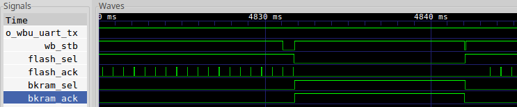
Let’s look specifically at the
serial output line o_wbu_uart_tx from the top level, and then from
within the top level, the
wishbone strobe
line wb_stb, the
flash_sel (flash
select) line, and then bkram_sel (block RAM select)
lines. As you may recall, wb_stb will be true anytime a request is being
made across the bus. The other two lines indicate when the address
associated with this request is either referencing the
flash
or the block RAM.
See a difference?
Here’s my figure for running without the DMA,
 |
and again for running with the DMA controller,
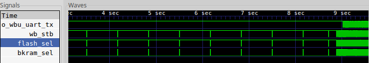 |
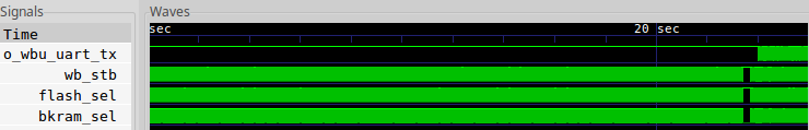
If you look at the far right, when o_wbu_uart_tx starts toggling that’s when
the first characters of the game are being sent to the serial port. This
doesn’t happen until the
ZipCPU
_bootloader has finished. Here, you can see that it takes about nine
seconds to copy everything from
flash
when using the _bootloader, whereas it
takes over twenty seconds without! You can also see a big difference in the
flash_sel and bkram_sel lines. What’s going on there?
Let’s drill one level deeper and look at what’s going on by zooming in.
Let’s also add the flash_ack and bkram_ack lines–there are the
wishbone acknowledgement
lines from these two peripherals, and indicate when a request has been
fulfilled.
You can see the trace without DMA, in Fig 5, below.
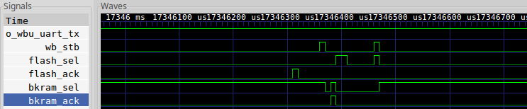 |
What’s not as readily apparent in this
trace
is the context–it begins in the middle of a transaction. A value has
already been requested from the
flash
controller by the time my screen capture starts. Once the
flash controller
acknowledges the transaction, that is when flash_ack goes high, the data
becomes available to the _bootloader,
and it immediately turns around and writes to the block RAM. Since the
block RAM is quite fast, it acknowledges its transaction almost immediately.
(Remember, transaction requests only take place when wb_stb is high, and
so Fig 6 only shows two transaction requests.) The
ZipCPU
then issues a read request of the
flash
and … everything stalls again waiting for the flash
controller’s
acknowledgement.
This is very different from what happens when the DMA, is turned on. For that case, you can see what happens when in Fig 6 below.
 |
In this case, the
DMA
reads multiple items from the
flash
in a back to back
fashion–you can see all of the acknowledgement’s in the flash_ack line
in Fig 6. During this time, the block RAM is idle. Once the
DMA
has finished
reading a rough 1k words from the
flash,
it then bursts these to the block
RAM. Look at the wb_stb line to see this–it’s nearly a constant ON
signal, indicating that one request after another is being made. In a
similar fashion, but unlike the
flash
controller’s
response, the block RAM’s acknowledgment signal is also a constant high–since
the block RAM can respond to one request per clock.
As a result, this portion of the copy goes by very quickly.
Given this information, would you rather copy your data using the DMA, or a tight loop within the ZipCPU?
How do I change the amount of block RAM?
Since I know this is going to come up, let me show you how easy it is to change the amount of block RAM in this device.
First, look in the AutoFPGA block ram configuration file. Within that file, find the line,
@$LGMEMSZ=20This line defines a tag, @LGMEMSZ, specifies that it is a numerical
tag with the @$ prefix, and then gives it the value of 20.
This tag is used to specify that the log, based two, of the block RAM
memory size is twenty–meaning it should have 1MB, or 2^20 bytes, of
block RAM. The key itself is unique to this
block ram configuration
file,
so you aren’t likely to find it elsewhere. It basically defines a local
variable within an AutoFPGA context.
However, with a bit of math and some substitution (remember,
AutoFPGA is primarily a
copy/paste utility with a calculator and address assignment built
in), this number becomes the amount of block RAM called for in the
system design.
You can change this one number, and then run make autodata from the main
directory (assuming you have
AutoFPGA installed and in your path),
and the design will immediately be reconfigured for the new memory size.
cd [path-to-zbasic]/
make autodata
Yes, you’ll still need to run make from the main directory again once
you’ve done this,
makeso that this newly configured design has a chance to build.
What changes?
Well, first, the @MAIN.INSERT tag that same
bkram.txt
file is used to tell
AutoFPGA what to place into your
main.v
file. In this case, it’s a reference to a
memdev
module which implements a block RAM device that is parameterized by its size.
@THIS.LGMEMSZ is used to control this parameter. It’s also used to
connect that design parameter to the number of address lines fed to this
component, and changing this size may cause the other peripherals on the bus
to be shuffled around to minimize the required bus logic.
Second, all of the addresses will (may) be re-assigned as I just mentioned.
This includes more than just the block RAM. These new addresses can be found
listed in the
regdefs.h
and
board.h
files based upon the @REGS.* and @BDEF.OSVAL tags.
Third, the linker definition
script
will have changed, which will adjust the
_bkram pointer used by the _bootloader we discussed above.
Fourth, the @SIM.LOAD tag defines the software necessary to load a program
into this memory, given the new location and length found in the updated
regdefs.h
file.
The result of all of this is that, following an AutoFPGA based reconfigure, all that is required is to rebuild the project and we have a new amount of memory at a (potentially) different location.
Next Steps
Now that you know how to run the ZBasic demonstration, the next step will be to show how simple and easy it is to add a new component using AutoFPGA, and then to demonstrate how we can integrate this component into our simulation and ultimately the FPGA design as a whole.
My current plan is to do this with the WBPMIC component. This particular controller is designed to control a MEMs audio microphone and A/D sold by Digilent–their “PMod MIC3”.
That will be our next step in this series, although there’s really a lot of information we can come back to–such as how the DMA controller works in the first place.
Wilt thou play with him as with a bird? or wilt thou bind him for thy maidens? (Job 41:5)