
Debugging AXI Streams
 |
The AXI Stream
protocol is a great way to move data around. Sure, like most
AXI related protocols, it’s a bit
bloated.
However, if you remove everything but the TVALID, TREADY, TDATA and
possibly TLAST or TUSER signals, then it really becomes quite usable.
Indeed, it’s a great protocol for just moving raw data around.
What such a simple AXI Stream offers over other protocols is the ability to ability to move data around a design with a simple handshake. Data can then move at the maximum speed the design is capable of, from one end of the design to another. Be aware, though, this is also one of it’s Achilles’ heels: You (as the engineer) need to be aware of what your data needs are, and you need to make certain that your stream processor can handle the throughput you need–but that’s another story.
Perhaps the biggest problem with AXI Stream processing is debugging it. Unlike peripherals, where once it passes a formal test you can just interact with them from a CPU until they “work”, the CPU doesn’t typically interact with streams directly. Streams are designed to “just do their thing”, and to do it at high speed in an unattended fashion.
The result is that I’ve seen a large number of individuals writing into (whatever) forum, complaining that an FFT isn’t working, when they really have no insight into what’s going on within their design. Yes, we’ve discussed this before. The typical set up starts with some sort of external signal generator, which is then connected to an on-board Analog to Digital Converter (A/D), which is then connected (through some processing chain) to an FFT, that is then connected to something else and possibly recorded. By starting the chain off with the signal generator, these users often judge that they’ve removed all of the unknowns in their problem. They then get stuck in FPGA Hell when this design doesn’t work. Often they’ll (wrongly) declare one of these components as not working, when really they have no insight into which component is either working or not.
Forgive me for saying this, but this is not how to debug an AXI Stream!
 |
Alternatively, I’ve seen individuals replace the input of the FFT with some form of NCO that they’ve never used before. They’ll then use Xilinx’s Internal Logic Analyzer to “check” the output (ignoring any AXI Stream signaling) and again wonder why their design isn’t working. While this setup has fewer unknowns, there are usually enough associated with different clock rates to render this design difficult to debug as well.
Again, this is not how to debug an AXI Stream.
Proper engineering process requires that you, as the designer and engineer, need to be able to separate components of your design and then to examine and debug each of them separately. Only after you know that each component is properly working should the various components be integrated together.
That’s problem one.
Problem two is that waveform trace’s aren’t really a good choice for debugging an AXI Stream. Sure, you can make it work, but the protocol is likely going to get in the way. You’ll be able to see both relevant, and irrelevant data samples. You’ll see both system clock periods of interest, and periods where the channel is stalled and the clock is not of interest. This will be confusing.
Indeed, we had this exact same problem some time ago when we examined our linear interpolation algorithm in a test bench. Consider, for example, Fig. 3 below which is drawn from Fig. 1 of that article.
 |
In this figure, the “correct” answer from the design is a linear ramp. Unfortunately, the outgoing signal isn’t valid on every cycle. As a result, the ramp appears to be broken. If you can remove the idle cycles, the ramp is no longer broken–making it easier to debug this design. Without removing these cycles, it becomes a challenge to simply understand the trace since the protocol kept getting in the way.
Today, let me offer another approach to stream debugging: controlling the stream from software located on a nearby processor–whether an on-board processor, or a nearby host connected over a serial port. From a non-real-time debugging standpoint it won’t make any difference–both will work.
AXI Stream Debugging – the Concept
The basic idea behind our approach is simple: we’ll create an AXI Stream debugger in the form of an AXI-lite bus slave that can feed data to our stream, and again receive data back again. An example of what this slave might look like is shown in Fig. 4.
 |
Such a debugger is not going to be a great choice for high speed processing, nor is it going to be a great choice for real-time processing. Instead, this will be a great choice for debugging a DSP processing chain where both ends of the chain can be found within the fabric of the FPGA. Once the processing chain has been properly debugged, and once you know it is working, then you can connect it to proper real-time components. In the meantime, let’s focus our debugging on one step of the problem at a time.
 |
Which step? Well, that’s up to you. Chances are you’ll want to place only one AXI Stream component between the source and the sink at first, then two, then on up to your whole chain.
So here’s how this will work:
-
Upon any reset, the entire chain will get cleared.
-
Your CPU program, either on a soft-core CPU located on the fabric or on a nearby host CPU over a debugging bus of some sort, will write to the core. Every word written to the core will enter into a FIFO, and eventually be flushed to the stream as illustrated in Fig. 4 above.
You (as the designer) will need to make certain that you don’t overload the FIFO, in the case of either a slow stream or one that will get stuck with back pressure. For this reason, we’ll make the FIFO size a user parameter that can be used to configure the core.
-
In order to be able to both generate data words with and without
TLASTset, we’ll reserve one address such that writes to that address will setTLAST, and a second address where writes do not setTLAST.For those not familiar with
TLAST, it’s an important part of stream burst or packet processing.TLASTneeds to be set on the last data word of any packet, and clear otherwise.As an example, consider Fig. 6 below, showing what transferring two packets using an AXI Stream might look like. In particular,
TLASTis set at the end of every packet.
 |
Unfortunately, this protocol is quite a bit different from the one I used
when building my own FFT.
Indeed, processing the TLAST signal properly was one of the hardest
parts of building an AXI Stream
interface to that FFT.
-
Handling data returns will start with polling the return FIFO to see how much data has been returned by the stream.
You can also poll the source FIFO to see how much data has been consumed, but we’ll get to that in a moment.
-
For any data that’s been returned to your program, you can then read the data back from the core and store it into memory, write it to the serial port via printf, write it to a file, whatever. Either way, it’s available for you to now inspect and debug.
-
If your test data set is exceptionally long, you can keep pushing data through the stream as long as space remains available in the return FIFOs to receive it.
Wouldn’t this be faster using an AXI MM2S core followed by an S2MM core? Absolutely! Our purpose in this exercise, however, isn’t speed–it’s debugging. By doing it this way, we remove the likelihood that something might go wrong in our setup of either of those cores. We also remove the likelihood that they will hang if ever something goes wrong–we’ll build our design so that we can catch those bugs instead.
Sound like a plan?
AXI Stream Properties
Some time ago, I was asked to write a set of formal properties to be used when verifying an AXI Stream core. You can find these properties on github if you are interested. Sadly, there are way more properties there than there are truly relevant ones. Also, just as with the AXI-lite and AXI(full) designs that we tested here, Xilinx’s AXI stream demo failed that test as well–but that’s another story for another day. So, instead, let’s focus on the minimum number of AXI Stream properties here, such as you might use in a basic stream processing system such as I’ve outlined in Fig. 4 above.
 |
We’ll limit ourselves to four signals: TVALID, TREADY, TDATA, and TLAST,
as shown in Fig. 6 on the right. Only the TDATA signal has any width to it,
and that width is user configurable. In our case, it’s width will be limited
by the width of the AXI-lite
bus–32’bits. That should be enough for most data processing applications.
The TVALID and TREADY registers have the meaning we are already familiar
with from our AXI handshaking
work. TVALID indicates
that the master has placed valid data on TDATA, and TREADY indicates that
the slave is ready to receive it. Data transfers whenever TVALID && TREADY
are both true on the same clock cycle. As with the other AXI handshaking
protocols,
TREADY needs to be registered.
The TLAST field is used by packet processing systems. Whenever TLAST is
true, the end of the packet has been received, and the next value will be the
first value in the next packet. This makes a lot of sense for networking
protocols, where packets are well defined. It also works nicely for
FFT
based processing, where a “packet” can be considered one frame of data.
 |
Be careful when working with TLAST, however: some Xilinx primitives will not
forward a packet of data unless TLAST is set. More than one engineer has
gotten stumped, wondering why his data is stuck in (some vendor core), when the
problem is simply that TLAST wasn’t set. For this reason, if your protocol
doesn’t need TLAST for a particular reason or purpose, then I recommend
leaving it set.
There’s one additional signal that gets some common usage that I haven’t listed
above, and that’s the TUSER data signal. This can be filled with whatever
you want to fill it with. As an example, it’s common to place HSYNC and/or
VSYNC data in this field, and actual pixel data in the TDATA field when
working with video. I haven’t
(yet) tried this myself, but it certainly seems reasonable to do. That said,
we won’t be supporting TUSER today. If your application needs a TUSER
field, then you’ll need to either modify our debugging
core
to generate it, or separate it from the TDATA field we will be generating.
Now with all this background, we can finally write a couple of AXI Stream properties. With just this simple definition above, they aren’t really all that complex.
First, valid must get cleared on any reset.
assert property (@(posedge S_AXI_ACLK)
	S_AXI_ARESETN |=> !M_AXI_TVALID);

assume property (@(posedge S_AXI_ACLK)
	S_AXI_ARESETN |=> !S_AXI_TVALID);
Here, I’m going to use the convention that signals beginning with M_AXIS_ are
AXI Stream
signals from the perspective of an
AXI Stream
master (source), whereas any signals beginning with S_AXIS_ are
AXI Stream
signals from the
perspective of the slave, the “sink” or consumer of the stream data.
If you want to rewrite this assertion using System Verilog’s immediate
assertions, things are roughly the same with the exception that you will need
an f_past_valid check to make certain are handling $past() properly.
initial f_past_valid = 1'b0;
always @(posedge S_AXI_ACLK)
	f_past_valid <= 1'b1;

always @(posedge S_AXI_ACLK)
if (!f_past_valid || !$past(S_AXI_ARESETN))
begin
	assert(!M_AXIS_TVALID);
	assume(!S_AXIS_TVALID);
end
The second important property is that !TREADY must stall the stream.
While the stream is stalled nothing
is allowed to change.
assert property (@(posedge S_AXI_ACLK)
	M_AXI_TVALID && !M_AXI_TREADY && S_AXI_ARESETN
	|=> M_AXI_TVALID && $stable(M_AXI_TDATA)
		&& $stable(M_AXI_TLAST));
You can see an example of how stalls might work in Fig. 6 above.
On its face, this one assertion captures everything remaining about this protocol. However, we can do better. The problem with this assertion is that you won’t be able to tell which of the three conditions failed without digging into the VCD trace that the tool generates. We can fix this by splitting this assertion into three separate assertions. Then, if any fails, we’ll know which of the three caused the problem.
assert property (@(posedge S_AXI_ACLK)
	M_AXI_TVALID && !M_AXI_TREADY && S_AXI_ARESETN
	|=> M_AXI_TVALID);

assert property (@(posedge S_AXI_ACLK)
	M_AXI_TVALID && !M_AXI_TREADY && S_AXI_ARESETN
	|=> $stable(M_AXI_TDATA));

assert property (@(posedge S_AXI_ACLK)
	M_AXI_TVALID && !M_AXI_TREADY && S_AXI_ARESETN
	|=> $stable(M_AXI_TLAST));
The slave assumptions are (almost) identical.
Each of these properties can easily be written using immediate assertions as well.
always @(posedge S_AXI_ACLK)
if (f_past_valid && $past(S_AXI_ARESETN)
	&& $past(M_AXI_TVALID && !M_AXI_TREADY))
begin
	assert(M_AXI_TVALID);
	assert($stable(M_AXI_TDATA));
	assert($stable(M_AXI_TLAST));

	// And if you are using TUSER
	// assert($stable(M_AXI_TUSER));
	// same for TID, TKEEP, and TSTRB
end
That’s about all you’ll need for verifying an AXI Stream.
 |
But let’s pause and think about these properties for a moment. While they are simple, there are some nasty consequences of using them. For example, …
-
What happens when the data is coming from a fixed data rate source, such as an A/D or a video source. If
TREADYis held low, it will be difficult to hold eitherTDATAorTLASTconstant. I mean, I suppose we could, but we’d be dropping data left and right. -
Likewise, what happens when the data is going to a fixed rate data sink? In that case, it would be important to us that
TVALIDbe true at some minimum rate or we would again fail our real-time requirement.
My point is simply this: the AXI Stream protocol doesn’t contain, within the protocol definition, your design’s data rate requirements. That requirement is critical, and probably dominates these rules above. You’ll need to handle that in an application dependent way.
Yes, an AXI Stream
property set could get much fancier. Indeed, when generating my own AXI
Stream properties
I did just that. I added in data counters and byte counters–since the full
AXI Stream protocol can transfer
TDATA values where only some of the data is relevant. I also added in data
rate checks, TID checks, and so on. If you want to use all
that,
feel free. All I’m saying today is that
the protocol
is a very powerful one, but it can be used quite easily if you use nothing more
beyond the handshaking
signals
outlined in Fig. 6 above.
The Basic Algorithm
There’s two basic halves to this algorithm, the write half and the read half.
Let’s walk through each and see how it works. In both cases, we’ll start from
our easy AXI-lite
example
and in particular from the axil_write_ready
and axil_read_ready signals that follow after the
skid buffers,
indicating that the
bus
wishes to either write or read data to or from our core.
Let’s start with the write half. Our
bus write transaction requests
will come from two
skid buffers, so that
a write request will be ready when both write
address
and write data
skid buffers have valid
data and the B* channel isn’t stalled. In this case, we’ll write data to our
core.
	assign	axil_write_ready = awskd_valid && wskd_valid
			&& (!S_AXI_BVALID || S_AXI_BREADY);
Then, based upon this axil_write_ready value, we’ll write to our
FIFO
if we ever write to the stream source write
address of our
core.
	assign	wfifo_write = axil_write_ready && awskd_addr == ADDR_SOURCE;

	sfifo #(.BW(C_AXIS_DATA_WIDTH), .LGFLEN(LGFIFO))
	source(.i_clk(S_AXI_ACLK), .i_reset(!S_AXI_ARESETN),
		.i_wr(wfifo_write),
		.i_data(wskd_data[C_AXIS_DATA_WIDTH-1:0]),
In this case, ADDR_SOURCE is the
address
we would write to in order to write a value to our outgoing stream.
We can then take the outputs of this FIFO, with very little modification, and turn them into AXI Stream signals.
		.i_rd(M_AXIS_TREADY),
			.o_data(M_AXIS_TDATA),
			.o_empty(wfifo_empty));

	always @(*)
		M_AXIS_TVALID = !wfifo_empty;
Okay, that was easy enough. How about the read half? In this case, our data would come in from an external stream source, and enter our core through a second FIFO. We’ll call this the “read FIFO” or “sink” simply because this is where the stream ends.
	always @(*)
		S_AXIS_TREADY = !rfifo_full;

	sfifo #(.BW(C_AXIS_DATA_WIDTH), .LGFLEN(LGFIFO))
	sink(.i_clk(S_AXI_ACLK), .i_reset(!S_AXI_ARESETN),
		.i_wr(S_AXIS_TVALID && S_AXIS_TREADY),
		.i_data(S_AXIS_TDATA),
		.o_full(rfifo_full), .o_fill(rfifo_fill),
That’s basic enough. Before we get to the second half, let’s discuss when we
want to read from our
FIFO.
For that, we’ll start with the axil_read_ready
signal from our
easy AXI-lite
design,
and generate a read signal for the
FIFO.
We’ll read, therefore, any time there’s a valid
address
and the result isn’t stalled.
	assign	axil_read_ready = arskd_valid
			&& (!S_AXI_RVALID || S_AXI_RREADY);
This read will come from the FIFO if we are ever reading from the stream sink register, and so we’ll read from the FIFO at that time.
assign read_rfifo =(axil_read_ready && arskd_addr== ADDR_SINK);The remaining details of the FIFO’s instantiation are now straightforward.
		.i_rd(read_rfifo),
			.o_data(rfifo_data),
			.o_empty(rfifo_empty));
You know, that’s not many changes to our simple AXI-lite design at all. Indeed, right at about this point in time, I started beating my chest thinking I’d built a truly awesome core for debugging stream designs.
Then I started writing the documentation for this core. The more I wrote, the more problems I could see it causing.
What happens, for example, if you have an FFT processing chain that requires four FFTs worth of data somewhere in the chain, but then only processes one sample of data every four clock cycles? Once the write FIFO is filled, what will happen to the new data values you write to this core?
They’ll fall off of the end of eternity and get lost.
 |
Oh, that’s bad.
So, let’s adjust our FIFO write signals so that we wait until there’s room in the FIFO before succeeding.
	assign	axil_write_ready = awskd_valid && wskd_valid
			&& (!S_AXI_BVALID || S_AXI_BREADY)
			&& ((awskd_addr != ADDR_SOURCE) || !wfifo_full);

	assign	wfifo_write = axil_write_ready && awskd_addr[1]==ADDR_SOURCE
			&& !wfifo_full;
There! Now, if the stream is a little slow in accepting our data, the write will wait until there’s room in the FIFO to accept it.
So, I went back to writing up the documentation for this core again.
Then I got to thinking, what happens if the incoming FIFO is full, and there’s no more room in the stream to accept any more values? The write request might then wait for an eternity.
No, that’s not good either.
So, let’s create a timeout. That way, when we generate this design, we can specify how long one should wait for a position in the source FIFO to become available before failing.
The timeout itself is just another counter. We’ll also use a signal,
write_timeout, to indicate that the counter has reached it’s limit and
we should abandon any writes.
	//
	// parameter OPT_TIMEOUT is the number of cycles to wait on either
	// read or write before giving up.
	//
	initial	write_timer = OPT_TIMEOUT-1;
	initial	write_timeout = 0;
	always @(posedge S_AXI_ACLK)
	if (!S_AXI_ARESETN)
	begin
		write_timer <= OPT_TIMEOUT-1;
		write_timeout<= 1'b0;
	end else if (!awskd_valid || !wskd_valid
			|| (awskd_addr != ADDR_SOURCE)
			|| (S_AXI_BVALID && !S_AXI_BREADY))
	begin
		write_timer <= OPT_TIMEOUT-1;
		write_timeout<= 1'b0;
	end else begin
		if (write_timer > 0)
			write_timer <= write_timer - 1;
		write_timeout <= (write_timer <= 1);
	end
Just to capture our intent with this write_timeout signal, we’ll quickly
scribe two assertions next to this write timeout logic.
	always @(*)
		assert(write_timer <= OPT_TIMEOUT-1);
	always @(*)
		assert(write_timeout == (write_timer == 0));
We can now adjust our internal write signal, indicating when we’ll accept a write request from the bus.
	assign	axil_write_ready = awskd_valid && wskd_valid
			&& (!S_AXI_BVALID || S_AXI_BREADY)
			&& ((awskd_addr != ADDR_SOURCE)
				|| (!wfifo_full || write_timeout));
This new logic just says that we’ll accept any writes to our core that aren’t going to the FIFO, or writes to the FIFO if it isn’t full, or we’ll accept them if the FIFO is full and we’ve timed out waiting.
But this also means we now have to figure out how to return a
bus
error
on a failed write. Let’s create an axil_berr for this new signal.
	always @(posedge S_AXI_ACLK)
	if (axil_write_ready)
		axil_berr <= (wfifo_full && awskd_addr == ADDR_SOURCE);
We can then use this signal to set S_AXI_BRESP to either an OKAY
response, or a SLVERR (slave error) response to the write request.
assign S_AXI_BRESP = { axil_berr, 1'b0 };Okay, so that’s pretty neat, only … what happens if wskd_strb was zero?
In particular, an AXI master is allowed to abort a
transaction it has issued
by clearing the WSTRB signal (wskd_strb after the
skid buffer in this
design) to all zeros. In that case, we aren’t going to want to write into our
FIFO
at all. So, let’s adjust our write to
FIFO
signal once more to capture this possibility.
	assign	wfifo_write = axil_write_ready && awskd_addr==ADDR_SOURCE
			&& wskd_strb != 0 && !wfifo_full;
At this point, we’re almost there. We’re just missing one last piece:
What about that TLAST signal? We need to make it so that this core can
set, or leave unset, the outgoing TLAST signal.
To handle this, we’ll borrow from the ADDR_SINK register. This is the
register we want to read from in order to read values from the stream sink
side of our design. We can then adjust our logic so that
writes to this ADDR_SINK register will leave the TLAST
signal clear whereas all other writes will set TLAST. If we set
our addresses
so that the two share an upper address bit, then our test for whether or not
we are writing will now be a test of awskd_addr[1] == ADDR_SOURCE[1] or not.
This is as far as I took the write logic.
You might notice that, other than checking for wskd_strb != 0, we’ve ignored
the WSTRB signal. This will be a problem if our AXI-lite slave is ever
driven from an AXI master
that’s only driving one octet or one half-word at a time. In that case, we’d
need to only write if wstrb[3] is set, and then record any partial words
written up until that point.
I’ll leave that to you as a homework problem.
Needless to say, I made the same (rough) improvements on the read side.
- Reads should only succeed if there’s data in the FIFO.
We’ll need to check for this as well. Therefore, if there’s no data in the read FIFO, the read request should wait for data and then timeout if it doesn’t come within a reasonable time frame.
	assign	axil_read_ready = arskd_valid
			&& (!S_AXI_RVALID || S_AXI_RREADY)
			&& ((arskd_addr[1] != ADDR_SINK[1])
|| (!rfifo_empty || read_timeout));- We’ll allow the user to read both from the
ADDR_SINKregister, and from the relatedADDR_SOURCEregister. In the case of reading fromADDR_SOURCE(which really isn’t the right read register), we’ll just return the next item of data without removing it from the FIFO. That’s the reason for the[1]in the (word) address logic above. It also explains the difference between the above example and the fullread_rfifologic below.
	assign	read_rfifo =(axil_read_ready && arskd_addr== ADDR_SINK)
&& !rfifo_empty;- The bus error logic, associated with an attempt to read that times out, is close enough to the write bus error logic that it doesn’t need to be discussed further in this overview.
That’s about all we’ll need to generate an AXI Stream, or to consume one, in an AXI-lite processing core.
Could we have done this with a full AXI processing core? Absolutely! But our goal today isn’t performance. If you want performance, use the MM2S and S2MM data movers respectively–don’t forget to coordinate your transfers in that case with the MMU, and to make certain that the cache stays coherent in the process.
Working with the core
Unfortunately, that’s not enough to work with this core.
Imagine, if you will, that you have some buffer of data you wish to send
to this core.
Let’s call this buffer, buf, and give it BUFLEN values. Let’s also assume
that our core can be found at the address in streamdbg, and that our
the FIFO has a length given by
FIFOLEN = 1<<LGFIFO. How would you go about writing BUFLEN values to
the core?
for(wpos=0; wpos < BUFLEN; wpos++)
	streamdbg[ADDR_SOURCE] = buf[wpos];
What will then happen if the FIFO fills up before you send the last data through? Your design will fail with a bus error. (We could have had it wait forever …) This is a “good” thing, but avoiding this problem altogether would be better.
What we’d really need is a way of knowing that there’s room enough in the FIFO for what we want to send to it, and then only write to it if there’s enough room. So, let’s allow for a FIFO status register, and let’s place our FIFO fill into the upper half of this register.
wpos = 0;
do {
	int available = (FIFOLEN - (streamdbg[ADDR_FIFO]>>16));
	int ln = (BUFLEN-wpos);
	if (ln > available)
		ln = available;
	for(k=0; k<ln; k++)
		streamdbg[ADDR_SOURCE] = buf[wpos++];
} while(wpos < BUFLEN);
That means we’ll need to add to our design the ability to read the write FIFO’s fill. Ok, got it.
What about reading from the core? A straightforward read might look like,
for(rpos=0; rpos < BUFLEN; rpos++)
	result[rpos] = streamdbg[ADDR_SINK];
Sadly, this will fail as well if the stream isn’t ready yet. We can repeat our last solution to handle this case if we’d like.
rpos = 0;
do {
	int available = (streamdbg[ADDR_FIFO] & 0x07fff)
	int ln = (BUFLEN-rpos);
	if (ln > available)
		ln = available;
	for(k=0; k<ln; k++)
		result[rpos++] = streamdbg[ADDR_SINK];
} while(rpos < BUFLEN);
What happens, though, if we are working with a stream loop from source to sink like we drew in Fig. 4, so that if we fail to read from the FIFO the resulting back pressure will eventually stop up the channel so far that we can’t write to it any more without generating a bus error? That would mean that for large enough data streams, you’d need to read and write at the same time.
This gets more complicated.
wpos = 0;
rpos = 0;
do {
	//
	// First, write whatever we can into the stream.
	//
	available = (FIFOLEN - (streamdbg[ADDR_FIFO]>>16));
	if (BUFLEN == wpos) {
		// Write zero values once we've filled the
		// pipeline
		for(k=0; k<available; k++)
			streamdbg[ADDR_SOURCE] = 0;
	} else {
		ln = (BUFLEN-wpos);
		if (ln > available)
			ln = available;
		for(k=0; k<ln; k++)
			streamdbg[ADDR_SOURCE] = buf[wpos++];
	}

	//
	// Now any reads
	//
	available = streamdbg[ADDR_FIFO] & 0x07fff;
	ln = (BUFLEN - rpos);
	if (ln > available)
		ln = available;
	for(k=0; k<ln; k++)
		result[rpos++] = streamdbg[ADDR_SINK];
} while(rpos < BUFLEN);
See how important it becomes to know how many items can be read from the FIFO? We’ll need to add that register to our design.
You may notice that we haven’t touched the TLAST element yet. Neither have
we sent any “end-of-packet” data, nor have we verified that end of packet data
is correct. In other words, we need to make it possible to read TLAST from
software. Since the meaning of TLAST varies from one application to the
next, I’ll put that capability in
this design,
but leave the software part as an exercise to the student.
AXI-lite to AXI-stream
Shall we take a look at what it takes to actually build this core? Let’s start at the top.
The design begins with a large comment block. At one time, I kept track of all design usage information in nearby “specification” sheets (PDFs). Perhaps I should return to that practice. Today, however, many of my component cores have large blocks of information in their headers. I also like to require that any such blocks describe the various registers used by the core, what their meaning is, and what happens when you read from or write to them.
I’m still somewhat torn about how to handle parameters. Should parameters be defined in the comment block above, or next to their actual definitions? I’ve done both. In this case, I define core parameters next to their definitions. Why? Because the information is then right where I will be when I go looking for it.
module	axil2axis #(
		//
		// Size of the AXI-lite bus.  These are fixed, since 1) AXI-lite
		// is fixed at a width of 32-bits by Xilinx def'n, and 2) since
		// we only ever have 4 configuration words.
		parameter	C_AXI_ADDR_WIDTH = 4,
		localparam	C_AXI_DATA_WIDTH = 32,
I’m somewhat torn over the data width and
address
parameters listed above. Specifically, should they be declared as
localparams or full blown parameters? Realistically, both of these should
be localparams, since they cannot be externally adjusted without breaking
the core within.
The width of the stream data signal is easier to change on the other hand.
		//
		// C_AXIS_DATA_WIDTH is the width of the TDATA elements on
		// the AXI streams.  This value can be anything between 1 and
		// the full width of the AXI-lite bus, 32.
		parameter	C_AXIS_DATA_WIDTH = 16,
I also decided to get a bit fancy, and make the stream source and sink
interfaces optional. OPT_SOURCE and OPT_SINK below just disconnect
any (relevant/costly) logic within from the various ports.
		//
		// OPT_SOURCE enables the AXI stream master logic.  If not
		// enabled, M_AXI_TVALID will be held at zero, and the stream
		// master logic may be ignored.
		parameter [0:0] OPT_SOURCE = 1'b1,
		//
		// OPT_SINK enables the AXI stream slave logic.  If not enabled,
		// reads will always return zero, and S_AXIS_TREADY will be
		// held high.
		parameter [0:0] OPT_SINK = 1'b1,
It can be annoying to read from a stream of 22-bits into a 32-bit value, only
to later need to adjust this 32-bit value to sign extend those last 10-bits.
This would be easier to do within the core, so we’ll set OPT_SIGN_EXTEND
for this purpose.
		//
		// If OPT_SIGN_EXTEND is set, values received will be sign
		// extended to fill the full data width on read.  Otherwise
		// the most significant of any unused bits will remain clear.
		parameter [0:0] OPT_SIGN_EXTEND = 1'b0,
The FIFO size is more interesting. The bigger the FIFO is, the easier it will be to send large blocks of data to this core. (Think network packets here, of FFT blocks.) FIFOs, however, use resources. Therefore, I’ve chosen to keep this FIFO’s resources at a minimum by default and set it to 5–the size that will fit into one Xilinx SLICEM per bit.
		//
		// Data written to this core will be placed into a FIFO before
		// entering the AXI stream master.  LGFIFO is the log, based
		// two, of the number of words in this FIFO.  Similarly, data
		// consumed by AXI stream slave contained in this core will go
		// first into a read FIFO.  Reads from the core will then return
		// data from this FIFO, or a bus error if none is available.
		parameter 	LGFIFO = 5,
Feel free to adjust this FIFO size as your application requires.
If you find yourself working with
my FFT,
you’ll know that you can configure the
FIFO
to handle one new value every clock cycle, one every other clock
cycle, or one every third clock cycle. Setting the OPT_TIMEOUT field to
4 (one extra, for good measure) in this case would be appropriate. You’ll
need to decide the right amount for your application, depending upon your
needs.
		//
		// OPT_TIMEOUT, if non-zero, will allow writes to the stream
		// master, or reads from the stream slave, to stall the core
		// for OPT_TIMEOUT cycles for the stream to be ready.  If the
		// stream isn't ready at this time (i.e. if the write FIFO is
		// still full, or the read FIFO still empty), the result will
		// be returned as a bus error.  Likewise, if OPT_TIMEOUT==0,
		// the core will always return a bus error if ever the write
		// FIFO is full or the read FIFO empty.
		parameter	OPT_TIMEOUT = 5,
If you don’t ever expect to write to a full
FIFO,
or try to read from a empty
FIFO,
you can safely set this OPT_TIMEOUT value to zero.
I’m also experimenting with an OPT_LOWPOWER option on all my cores. We’ve
discussed this a bit before. Since one source of power used by a design is
the power required to change logic wires, I have this OPT_LOWPOWER option
for use in holding any unused values to zero.
		//
		// OPT_LOWPOWER sets outputs to zero if not valid.  This applies
		// to the AXI-lite bus, however, and not the AXI stream FIFOs,
		// since those don't have LOWPOWER support (currently).
		parameter [0:0]	OPT_LOWPOWER = 0,
This “lowpower” option may also make it easier to “see” things in a VCD trace display.
At some point in time, I’d like to come back and revisit these settings to see if adjusting them actually does lower power usage. Until that time, I’m just slowly accumulating these values.
Skipping past the port definitions, I’m going to define four (word-based) addresses for this core:
	localparam	[1:0]	ADDR_SINK = 2'b00,	// Read from stream
				ADDR_SOURCE = 2'b01, // Write, also sets TLAST
				ADDR_STATS  = 2'b10,
				ADDR_FIFO   = 2'b11;
I also find Xilinx’s C_FULL_VARIABLE_NAME convention cumbersome to use.
Sure, it’s great for documenting code, but I’ll just rename the stream width
to SW for internal usage here. You can search the code for the definition
of SW and then get the best of both worlds.
localparam SW = C_AXIS_DATA_WIDTH;We can then skip the rest of the module definition, and jump right to the bus write processing. For the most part, I just copied the bus processing logic from the easy AXI-lite article. Notice below, for example, that I’m only keeping the full word address. One other change I made was to remove the skid buffer option. If you are writing to a stream, you’ll want to be able to write as fast as your bus infrastructure will allow you to–since that will be the bottleneck in your testing design, and one of the big differences between test and real performance.
	skidbuffer #(.OPT_OUTREG(0),
			.OPT_LOWPOWER(OPT_LOWPOWER),
			.DW(C_AXI_ADDR_WIDTH-ADDRLSB))
	axilawskid(//
		.i_clk(S_AXI_ACLK), .i_reset(i_reset),
		.i_valid(S_AXI_AWVALID), .o_ready(S_AXI_AWREADY),
		.i_data(S_AXI_AWADDR[C_AXI_ADDR_WIDTH-1:ADDRLSB]),
		.o_valid(awskd_valid), .i_ready(axil_write_ready),
		.o_data(awskd_addr));

	skidbuffer #(.OPT_OUTREG(0),
			.OPT_LOWPOWER(OPT_LOWPOWER),
			.DW(C_AXI_DATA_WIDTH+C_AXI_DATA_WIDTH/8))
	axilwskid(//
		.i_clk(S_AXI_ACLK), .i_reset(i_reset),
		.i_valid(S_AXI_WVALID), .o_ready(S_AXI_WREADY),
		.i_data({ S_AXI_WDATA, S_AXI_WSTRB }),
		.o_valid(wskd_valid), .i_ready(axil_write_ready),
		.o_data({ wskd_data, wskd_strb }));
Now that we’ve gotten through the
skid buffers,
the rest of the design will
handle write processing based upon the axil_write_ready signal below.
This signal guarantees that we don’t try processing a signal until both write
address
and write data are ready. It also makes certain that we don’t drop
data packets, by double checking that the output isn’t stalled with a return
response that’s not getting accepted. Finally, we’ll stall a write to the
FIFO if ever the
FIFO is full–just up until
a write timeout.
	assign	axil_write_ready = awskd_valid && wskd_valid
			&& (!S_AXI_BVALID || S_AXI_BREADY)
			&& ((awskd_addr[1] != ADDR_SOURCE[1])
				|| (!wfifo_full || write_timeout));
This signal is key to a lot of the processing that follows. It’s worth noting that it only requires 8-inputs, so it should only cost one MUX8 to calculate. Well, not quite. Those skid buffer valid signals are also combinatorial. Therefore, when counting logic, be aware that you are probably two layers deep into combinatorial logic on your way to the next flip-flop whenever you use this signal. If this is a problem, you can register the skid buffer outputs.
Now let’s look at how to handle the write timeouts.
	generate if ((OPT_TIMEOUT > 0) && OPT_SOURCE)
	begin
We’ll start our timeout counter, write_timer, at OPT_TIMEOUT-1
if ever the bus is idle. We’ll also return write_timeout to zero
at this time.
		always @(posedge S_AXI_ACLK)
		if (!S_AXI_ARESETN)
		begin
			write_timer <= OPT_TIMEOUT-1;
			write_timeout<= 1'b0;
Then, any time the bus isn’t yet ready to issue a write, or any time we have written to the bus successfully, then we’ll reset the timer to it’s full length.
		end else if (!awskd_valid || !wfifo_full || !wskd_valid
				|| (awskd_addr[1] != ADDR_SOURCE[1])
				|| (S_AXI_BVALID && !S_AXI_BREADY))
		begin
			write_timer <= OPT_TIMEOUT-1;
			write_timeout<= 1'b0;
Finally, if we are stalled waiting for the
FIFO
to accept new data, then count down. Once we get to zero, set the
write_timeout value so we can accept the write anyway and just return a
bus
error.
		end else begin
			if (write_timer > 0)
				write_timer <= write_timer - 1;
			write_timeout <= (write_timer <= 1);
		end
Just to make certain we built this relationship properly, we’ll stuff our
two assertions in here before leaving the generate block. The ifdef
will keep the assertions from being examined by the synthesizer.
`ifdef	FORMAL
		always @(*)
			assert(write_timer <= OPT_TIMEOUT-1);
		always @(*)
			assert(write_timeout == (write_timer == 0));
`endif
	end else begin
Finally, if either we aren’t supporting timeouts, or if we aren’t supporting
a stream source/master interface, then let’s make certain that the
write_timeout is always true–that way we’ll never wait if the
FIFO
is busy.
		always @(*)
			write_timeout<= 1'b1;

	end endgenerate
The BVALID logic is almost identical to our
easy AXI-lite
example.
The only difference between the two here is hidden in the axil_write_ready
signal above.
	initial	axil_bvalid = 0;
	always @(posedge S_AXI_ACLK)
	if (i_reset)
		axil_bvalid <= 0;
	else if (axil_write_ready)
		axil_bvalid <= 1;
	else if (S_AXI_BREADY)
		axil_bvalid <= 0;

	assign	S_AXI_BVALID = axil_bvalid;
The last piece of the write signaling is the
bus
error.
AXI supports
four bus responses: 2'b00 OKAY, 2'b01 EXOKAY, 2'b10 SLVERR, and
2'b11 DECERR. AXI-lite slaves aren’t allowed to return EXOKAY signals,
and decode
errors
really only make sense if returned by the
interconnect.
Therefore, we’ll return either OKAY, if everything works well, or SLVERR
if we timeout while waiting for space in
the FIFO.
	initial	axil_berr = 0;
	always @(posedge S_AXI_ACLK)
	if (OPT_LOWPOWER && i_reset)
		axil_berr <= 0;
	else if (axil_write_ready)
		axil_berr <= (wfifo_full)&&(awskd_addr[1]==ADDR_SOURCE[1]);
	else if (OPT_LOWPOWER && S_AXI_BREADY)
		axil_berr <= 1'b0;

	assign	S_AXI_BRESP = { axil_berr, 1'b0 };
The logic above is really much simpler than it looks. If we are responding to
a write, then we generate an error if the
FIFO
was full and the write was to be to our stream source location. The
rest of the logic just clears our
bus
error
signal so that it will only ever be set if BVALID is also set.
If you keep OPT_LOWPOWER clear, this logic will quietly vanish.
That brings us to our stream source write
FIFO.
We’ll want to write to this
FIFO
on any write to the stream source registers for our
core.
There are only two exceptions, both discussed above. The first is that we
won’t attempt to write if the
FIFO
is full–even if the write was accepted (i.e. it timed out). Second, we’ll
only write to the
FIFO
if the WSTRB signal associated with this data is not zero.
	assign	wfifo_write = axil_write_ready && awskd_addr[1]==ADDR_SOURCE[1]
			&& wskd_strb != 0 && !wfifo_full;
The stream source
FIFO
should look similar, if not identical, to what we
discussed above. The biggest difference is that we’ve now added the TLAST
information, and placed the entire
FIFO
logic into a generate block. The generate block will help us remove all of
this extra logic if we won’t be connecting to an
AXI Stream
consumer in the first place.
	generate if (OPT_SOURCE)
	begin

		sfifo #(.BW(SW+1), .LGFLEN(LGFIFO))
		source(.i_clk(S_AXI_ACLK), .i_reset(!S_AXI_ARESETN),
			.i_wr(wfifo_write),
			.i_data({awskd_addr[0],
					wskd_data[SW-1:0]}),
			.o_full(wfifo_full), .o_fill(wfifo_fill),
			.i_rd(M_AXIS_TREADY),
				.o_data({ M_AXIS_TLAST, M_AXIS_TDATA }),
				.o_empty(wfifo_empty));

		always @(*)
			M_AXIS_TVALID = !wfifo_empty;

	end else begin
In case the user kept the OPT_SOURCE parameter clear, we’ll just quietly
and carefully not generate any outgoing stream data.
		always @(*)
		begin
			M_AXIS_TVALID = 1'b0;
			M_AXIS_TDATA  = 0;
			M_AXIS_TLAST  = 0;
		end

		assign	wfifo_full = 1'b0;
		assign	wfifo_fill = 0;

	end endgenerate
That’s the write FIFO which generates an AXI Stream source. Indeed, that really completes the whole write half of the core.
The next step is the read FIFO where we read data from the incoming stream. As with the write FIFO, we’re using a generate block to allow us to easily remove the FIFO, if it won’t actually be used.
	generate if (OPT_SINK)
	begin

		sfifo #(.BW(SW+1), .LGFLEN(LGFIFO))
		sink(.i_clk(S_AXI_ACLK), .i_reset(!S_AXI_ARESETN),
Writing to the FIFO, is really easy. Indeed, we really don’t need to adjust the AXI handshaking signals (much).
			.i_wr(S_AXIS_TVALID && S_AXIS_TREADY),
			.i_data({S_AXIS_TLAST, S_AXIS_TDATA}),
			.o_full(rfifo_full), .o_fill(rfifo_fill),
Our biggest problem will be that the FIFO returns an FULL signal when what we want is a READY signal. We’ll fix that in just a moment.
For now, notice that reading from the
FIFO
depends upon a read_rfifo signal. That and rfifo_empty are the
key signals here.
			.i_rd(read_rfifo),
				.o_data({ rfifo_last, rfifo_data }),
				.o_empty(rfifo_empty));
I said above that we needed a READY signal rather than a FULL signal. Converting between the two on an FPGA. is really a no-cost operation, since it will get absorbed into whatever LUT it goes to next.
		always @(*)
			S_AXIS_TREADY = !rfifo_full;
Now for the key signal. We’ll read from this
FIFO
on three conditions.
The first, most obvious one, is that a bus read must have been requested and
accepted. The second condition is that we must be reading from the ADDR_SINK
data address,
and third, that there must be data there. If not, any read would fail.
		assign	read_rfifo =(axil_read_ready && arskd_addr== ADDR_SINK)
				&& !rfifo_empty;

	end else begin
Finally, if we aren’t implementing a stream sink/slave, we’ll just idle all of these lines.
		always @(*)
			S_AXIS_TREADY = 1'b1;

		assign rfifo_empty = 1'b1;
		assign rfifo_data  = 0;
		assign rfifo_last  = 1'b1;
		assign rfifo_fill  = 0;

	end endgenerate
The key here is that we want to leave TREADY high–in case someone
accidentally connects
this core
to a real
AXI Stream.
This way, we won’t stall that stream.
Read timeout processing is almost identical to the write timeouts discussed above.
	generate if (OPT_SINK && OPT_TIMEOUT > 0)
	begin
		// ...
		always @(posedge S_AXI_ACLK)
		if (!S_AXI_ARESETN)
		begin
			read_timer <= OPT_TIMEOUT-1;
			read_timeout<= 1'b0;
		end else if (!arskd_valid || (S_AXI_RVALID && !S_AXI_RREADY)
				||!rfifo_empty
				||(arskd_addr[1] != ADDR_SINK[1]))
		begin
			read_timer <= OPT_TIMEOUT-1;
			read_timeout<= 1'b0;
		end else begin
			if (read_timer > 0)
				read_timer <= read_timer - 1;
			read_timeout <= (read_timer <= 1);
		end

`ifdef	FORMAL
		always @(*)
			assert(read_timer <= OPT_TIMEOUT-1);
		always @(*)
			assert(read_timeout == (read_timer == 0));
`endif
	end else begin

		always @(*)
			read_timeout = 1'b1;

	end endgenerate
Now that we have our read FIFO squared away, let’s look at what it will take to handle the AXI-lite signaling. The first step, as we’ve discussed in the easy AXI-lite article, is to run the read request into a skid buffer.
	skidbuffer #(.OPT_OUTREG(0),
			.OPT_LOWPOWER(OPT_LOWPOWER),
			.DW(C_AXI_ADDR_WIDTH-ADDRLSB))
	axilarskid(//
		.i_clk(S_AXI_ACLK), .i_reset(i_reset),
		.i_valid(S_AXI_ARVALID), .o_ready(S_AXI_ARREADY),
		.i_data(S_AXI_ARADDR[C_AXI_ADDR_WIDTH-1:ADDRLSB]),
		.o_valid(arskd_valid), .i_ready(axil_read_ready),
		.o_data(arskd_addr));
When shall we accept a value from this skid buffer? Unlike the AXI write side, we don’t need to wait for both valid write address and write data, we can read if ever there’s a valid read address request. That’s the first part. The second part is that we can’t read until the last result has been cleared. If there’s back pressure on the return, we’ll need to wait. Finally, if the user wishes to read from the stream sink FIFO and the FIFO is empty, then we’ll wait. If no data shows up, we’ll time out and return a bus error.
	assign	axil_read_ready = arskd_valid
			&& (!S_AXI_RVALID || S_AXI_RREADY)
			&& ((arskd_addr[1] != ADDR_SINK[1])
				|| (!rfifo_empty || read_timeout));
The RVALID signal should look identical to the
easy AXI-lite
example, and
indeed to the BVALID signal above. The big difference is that there’s
more logic stuffed into the axil_read_ready signal than there was in our
easy AXI-lite
example.
	initial	axil_read_valid = 1'b0;
	always @(posedge S_AXI_ACLK)
	if (i_reset)
		axil_read_valid <= 1'b0;
	else if (axil_read_ready)
		axil_read_valid <= 1'b1;
	else if (S_AXI_RREADY)
		axil_read_valid <= 1'b0;

	assign	S_AXI_RVALID = axil_read_valid;
As with BRESP, we’ll generate a
bus
error
on any attempt to read from an empty
FIFO,
after a timeout. Otherwise all read responses should return an OKAY
no error response (2’b00).
	always @(posedge S_AXI_ACLK)
	if (OPT_LOWPOWER && !S_AXI_ARESETN)
		axil_rerr <= 1'b0;
	else if (axil_read_ready)
		axil_rerr <= rfifo_empty && (arskd_addr[1] == ADDR_SINK[1]);
	else if (OPT_LOWPOWER && S_AXI_RREADY)
		axil_rerr <= 1'b0;

	assign	S_AXI_RRESP = { axil_rerr, 1'b0 };
At this point, we’ve defined three registers. There’s the two stream
source register–one clearing TLAST and one setting it. Those registers
are shared by the two stream sink registers, one peeking at the
FIFO
and the other reading from it. There’s also the
FIFO
fill status register we discussed above. There’s one more register position
available to us.
Why not implement a counter, to count how much data has been received from the various streams?
Let’s count two things: First, we’ll count the number of data words transmitted
or received on each channel. Second, we’ll count the number of TLASTs on
each channel. Since we don’t really have a way of keeping these counters from
overflowing, we’ll just accept that as a general consequence that the user
will need to handle.
Here’s the logic for the read counters. First, they get cleared on reset.
	initial	reads_completed = 0;
	initial	read_bursts_completed = 0;
	always @(posedge S_AXI_ACLK)
	if (!S_AXI_ARESETN)
	begin
		reads_completed <= 0;
		read_bursts_completed <= 0;
If we haven’t implemented the read sink, then we’ll count whether any data comes in that interface anyway. It’s just dropping on the floor, but it might be worth knowing it was there in the first place.
	end else if (!OPT_SINK)
	begin
		reads_completed <= reads_completed + (S_AXIS_TVALID ? 1:0);
		read_bursts_completed <= read_bursts_completed
				+ ((S_AXIS_TVALID && S_AXIS_TLAST) ? 1:0);
Otherwise, we’ll count values received every time we read from the FIFO.
	end else if (read_rfifo && !rfifo_empty)
	begin
		reads_completed <= reads_completed + 1;
		read_bursts_completed <= read_bursts_completed + (rfifo_last ? 1:0);
	end
The write counters are almost identical.
	generate if (OPT_SOURCE)
	begin

		initial	writes_completed = 0;
		initial	write_bursts_completed = 0;
		always @(posedge S_AXI_ACLK)
		if (!S_AXI_ARESETN)
		begin
			writes_completed <= 0;
			write_bursts_completed <= 0;
Where the write counters differ is that we’ll count values leaving our core rather than values written into our source FIFO.
		end else if (M_AXIS_TVALID && M_AXIS_TREADY)
		begin
			writes_completed <= writes_completed + 1;
			write_bursts_completed <= write_bursts_completed
					+ (M_AXIS_TLAST ? 1:0);
		end

	end else begin
Since we are the source of this second stream, then the counter would be meaningless if the source functionality wasn’t enabled. In that case, we’ll just hold the counters at zero.
		always @(*)
		begin
			writes_completed = 0;
			write_bursts_completed = 0;
		end

	end endgenerate
The last important part of this core is the data read from it.
	initial	axil_read_data = 0;
	always @(posedge S_AXI_ACLK)
	if (OPT_LOWPOWER && !S_AXI_ARESETN)
		axil_read_data <= 0;
The first rule of read data is that it can only change if the
AXI-lite bus
isn’t stalled. By gating on !RVALID || RREADY we guarantee that we’ll
meet this rule of the road.
	else if (!S_AXI_RVALID || S_AXI_RREADY)
	begin
Now let’s walk through the registers that we might wish to read from.
If we read from the stream at all, we’ll be reading from the
FIFO. This will be true
for both the “correct” address–which will remove a value from the
FIFO upon being read–as well
as the ADDR_SOURCE address–which will just allow us to peek at the read
data.
		axil_read_data <= 0;
		casez(arskd_addr)
		{ ADDR_SINK[1], 1'b? }:	begin
			if (OPT_SIGN_EXTEND && rfifo_data[SW-1])
				axil_read_data <= -1;
			axil_read_data[SW-1:0] <= rfifo_data;
			end
Since we started this block by setting every bit to zero, we’ll only adjust
bits here that are defined by the stream. The exception is if we want to
sign extend our data. In that case, and if the data value has its sign bit
set, then we’ll set everything to 1'b1 before rewriting the correct values
to the stream bits.
That brings us to our statistics register, containing counts of data received and transmitted. This is straightforward. The burst counters are four bits each, and the word counters are 12-bits each. We just form a word to return here from them.
		ADDR_STATS: begin
			axil_read_data[31:28] <= write_bursts_completed;
			axil_read_data[27:16] <= writes_completed;
			axil_read_data[15:12] <= read_bursts_completed;
			axil_read_data[11:0]  <= reads_completed;
			end
After the statistics register is the
FIFO
fill register. For this register, we’ll report the write (source)
FIFO’s
fill in the top 16 bits, and the read (sink)
FIFO’s
fill in the bottom 15-bits. In many ways, it’s unlikely that our
FIFO
size will ever be 32768 elements corresponding to 128kB–the
maximum size that could be reported here. Block RAM is just too precious
to place all of it here. Therefore, we can steal one of those bits to return
a TLAST value from our stream sink.
		ADDR_FIFO:	begin
			// FIFO information
			axil_read_data[16 +: LGFIFO+1] <= wfifo_fill;
			axil_read_data[15] <= rfifo_last;
			axil_read_data[LGFIFO:0] <= rfifo_fill;
			end
		endcase
As one final touch, if nothing’s reading from the core, and if we are building an (unproven) “low power” design, then we’ll clear the read data register.
		if (OPT_LOWPOWER && !axil_read_ready)
			axil_read_data <= 0;
	end

	assign	S_AXI_RDATA  = axil_read_data;
That ends the basic logic for this core.
But how shall we know that it works?
Verification
Here, we turn to formal methods.
Have I tested this core in simulation yet? In hardware? No, not at this point. Still, here are the properties I have.
First, we’ll always assume that we start up with the reset active.
	initial	f_past_valid = 0;
	always @(posedge S_AXI_ACLK)
		f_past_valid <= 1;

	always @(*)
	if (!f_past_valid)
		assume(!S_AXI_ARESETN);
That was easy.
What else might we do?
We can include our AXI-lite formal property set.
	faxil_slave #(
		.C_AXI_DATA_WIDTH(C_AXI_DATA_WIDTH),
		.C_AXI_ADDR_WIDTH(C_AXI_ADDR_WIDTH),
		.F_LGDEPTH(F_AXIL_LGDEPTH),
		.F_AXI_MAXWAIT(OPT_TIMEOUT + 2),
		.F_AXI_MAXDELAY(OPT_TIMEOUT + 2),
		.F_AXI_MAXRSTALL(2),
		.F_OPT_COVER_BURST(4)
	) faxil(
		.i_clk(S_AXI_ACLK), .i_axi_reset_n(S_AXI_ARESETN),
		//
		.i_axi_awvalid(S_AXI_AWVALID),
		.i_axi_awready(S_AXI_AWREADY),
		.i_axi_awaddr( S_AXI_AWADDR),
		.i_axi_awcache(4'h0),
		.i_axi_awprot( S_AXI_AWPROT),
		//
		.i_axi_wvalid(S_AXI_WVALID),
		.i_axi_wready(S_AXI_WREADY),
		.i_axi_wdata( S_AXI_WDATA),
		.i_axi_wstrb( S_AXI_WSTRB),
		//
		.i_axi_bvalid(S_AXI_BVALID),
		.i_axi_bready(S_AXI_BREADY),
		.i_axi_bresp( S_AXI_BRESP),
		//
		.i_axi_arvalid(S_AXI_ARVALID),
		.i_axi_arready(S_AXI_ARREADY),
		.i_axi_araddr( S_AXI_ARADDR),
		.i_axi_arcache(4'h0),
		.i_axi_arprot( S_AXI_ARPROT),
		//
		.i_axi_rvalid(S_AXI_RVALID),
		.i_axi_rready(S_AXI_RREADY),
		.i_axi_rdata( S_AXI_RDATA),
		.i_axi_rresp( S_AXI_RRESP),
		//
		.f_axi_rd_outstanding(faxil_rd_outstanding),
		.f_axi_wr_outstanding(faxil_wr_outstanding),
		.f_axi_awr_outstanding(faxil_awr_outstanding)
		);
It’s unfortunate that instantiating this property set takes so much typing. Half of the proof is captured by that property set. In other words, we’re half way home already. A simple formal verification run at this point would prove that we are AXI-lite bus compliant–that we haven’t messed anything up.
If you looked closely, you might have noticed that this setup above was
almost identical to the setup from our
easy AXI-lite
example.
The difference was included in the two configuration parameters, F_AXI_MAXWAIT
and F_AXI_MAXDELAY. These parameters capture the maximum amount of time
our core
should ever take to respond to the
bus. In order to support a
timeout of OPT_TIMEOUT clocks, we needed to extend these values somewhat.
Other than that–no changes.
The same goes for the
induction
assertions. The only change that’s meed made to these assertions is that
I’ve removed the OPT_SKIDBUFFER option. In all other respects, these
following lines are unchanged.
	always @(*)
	begin
		assert(faxil_awr_outstanding== (S_AXI_BVALID ? 1:0)
			+(S_AXI_AWREADY ? 0:1));

		assert(faxil_wr_outstanding == (S_AXI_BVALID ? 1:0)
			+(S_AXI_WREADY ? 0:1));

		assert(faxil_rd_outstanding == (S_AXI_RVALID ? 1:0)
			+(S_AXI_ARREADY ? 0:1));
	end
At this point, we should be able to pass an induction check to know that our core fully implements the AXI-lite specification: No CPU will hang trying to read from this core.
Let’s move on to our AXI Stream properties.
Remember how we had two properties? First, TVALID must drop following any
reset.
	always @(posedge S_AXI_ACLK)
	if (!f_past_valid || !$past(S_AXI_ARESETN))
	begin
		assume(!S_AXIS_TVALID);
Second, if the stream is ever stalled, TVALID should remain high and any
associated data should stay constant.
	end else if ($past(S_AXIS_TVALID && !S_AXIS_TREADY))
	begin
		assume(S_AXIS_TVALID);
		assume($stable(S_AXIS_TDATA));
		assume($stable(S_AXIS_TLAST));
	end
Here, we’ve assumed these properties following my “master rule of formal verification”: Assume inputs, assert local state and outputs. Since these signals are inputs to our design, they are assumed.
That also means that we’ll need another block where we assert these same properties of our output going stream.
	always @(posedge S_AXI_ACLK)
	if (!f_past_valid || !$past(S_AXI_ARESETN))
	begin
		assert(!M_AXIS_TVALID);
	end else if ($past(M_AXIS_TVALID && !M_AXIS_TREADY))
	begin
		assert(M_AXIS_TVALID);
		assert($stable(M_AXIS_TDATA));
		assert($stable(M_AXIS_TLAST));
	end
Voila! We now know this core will obey the rules of the road for both AXI-lite and AXI Stream protocols.
But how well does
this core
work? For that, we’ll turn to a cover() check.
Cover Checks
Once a core I’m working with passes it’s formal properties via induction, I
next turn to cover().
This is usually my last step before qualifying a core for integrated
simulation
testing.
What sorts of things should we test? We’ll, I’d like to know what kind of throughput our AXI Stream source might achieve.
always @(*)
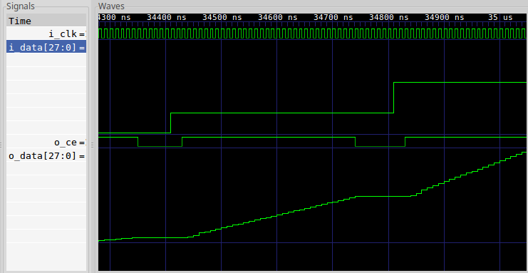
cover(S_AXI_ARESETN && writes_completed == 16);From this one statement, I get the trace shown in Fig. 11 below.
 |
As designed, values written to the core are available on the outgoing stream one clock later.
I can then repeat this same test on the stream sink side of the design.
	always @(*)
		cover(S_AXI_ARESETN && reads_completed == 16);
As before, this one statement returns a valuable trace. This time, I get the trace shown in Fig. 12 below.
 |
This trace is a little more interesting. In this case, the first read attempt stalled. Why? Because it takes a clock for data to pass from the incoming stream, through the FIFO, to where it can be read. The neat part is, our design stalls properly as designed during this one extra cycle, before returning the requested value.
Pretty cool, huh?
How about a bus error? Does my timeout logic work? Can I generate a bus error on the stream source side of the design?
	always @(*)
		cover(S_AXI_BVALID && S_AXI_BRESP != 2'b00);
Sure enough, Fig. 13 shows what a stream source bus error might look like.
 |
Yes, I shortened the size of the FIFO to only four elements make it easier to generate this trace.
In the trace, four values are written to the stream. That’s enough to fill up
the FIFO. Since the stream
slave holds M_AXIS_TREADY low, none of these values leaves the
FIFO. Then, when we try to
write the fifth value, D4 to
the core,
it has to stall. There’s no where for this value to go. After stalling
for four cycles,
the core
produces the desired
bus
error on the fifth cycle.
Let’s repeat the same check on the stream sink side of the core. What would it take to achieve a bus error on that side?
Again, the cover() statement is very easy to write.
	always @(*)
		cover(S_AXI_RVALID && S_AXI_RRESP != 2'b00);
In this case, it’s a lot easier to generate a bus error. Unlike generating a bus error on the stream source side, we don’t have to wait for the FIFO to fill. Read bus errors are instead generated when the FIFO is empty–such as it would be in it’s initial condition.
This trace is shown in Fig. 14 below.
 |
Conclusion
When students come to me to ask, how shall I do XYZ with an FPGA? My response is usually that you need to start with some scaffolding, and then to X, then Y, and then Z. Today’s design is an example of what such scaffolding might look like. It’s not a design that you’d use within any final product. However, it’s a design that you might need to use on your way towards getting there.
Behold, this have I found, saith the preacher, counting one by one, to find out the account (Eccl 7:27)