
Buidilng an AXI-Lite slave the easy way
Since writing my first two articles on AXI-Lite, the first discussing how to verify the an AXI-Lite interface and the second how to build an AXI-Lite slave, I’ve had the opportunity to build not just one but several AXI-Lite slaves. (1, 2, 3, 4, 5, 6, etc.) The cool part is, I’ve come across some really easy ways to do it that I thought might be worth sharing.
Before we start, one warning:
If you are interested in building an AXI-Lite slave the easy way, don’t start with vendor IP! It’s broken. Xilinx’s AXI-Lite demo code has been broken since at least 2016. They’ve promised fixes in 2020, but I haven’t seen them yet. Intel’s designs are also broken (as is their forum or I might’ve reported the bugs).
No, the place to start is with a formal property file. From there, you can either use a skid buffer or not, your choice, depending upon the performance you want from your AXI-lite slave. In both cases, though, we’re going to look today at how easy we can make building an AXI-Lite slave.
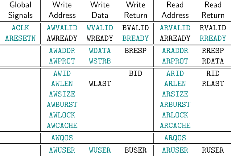 |
As you follow along below, consider the chart showing the various AXI signal
names shown in Fig. 1 on the right. The chart is organized into columns by
channel: there’s the write address channel with signals prefixed by AW,
the write data channel with signals prefixed by W, the write return
channel with signals prefixed by B, the read address channel with signals
prefixed by AR and the read return channel with signals prefixed by R.
In our slave below, we’ll follow Xilinx’s example and add the additional
prefix S_AXI_.
The top row of this chart shows the pair of handshaking signals, *VALID and
*READY, required for controlling data flow on each channel.
The next row shows the AXI-Lite signals we’ll be working with today. The
three rows below that show AXI signals that aren’t a part of the AXI-lite
protocol.
Our goal will be to control a set of internal registers to our core, while also replying to the bus via the various AXI-Lite signals shown in black in Fig. 1.
Four Registers
For the sake of today’s discussion, let’s allow our slave to have four
registers. We’ll call them r0, r1, r2 and r3.
reg [C_AXI_DATA_WIDTH-1:0] r0, r1, r2, r3;Please, before we go further though, don’t embarrass me. If you copy this logic
for your own designs (and I expect you might), rename these registers! I’ve
just seen too many folks starting with Xilinx’s AXI-Lite demonstration
design
that then leave their registers named
stupid things like slv_reg0, slv_reg1, etc. While that might be great for
a demonstration design, it’s completely inappropriate for any practical designs.
Indeed, if you look at some of my own
examples, you’ll see I’ve given my own
registers names
that match closer to their meaning. For example, cmd_abort (user has
commanded an abort), r_busy (the core is busy working), cmd_addr (the
address to write to), cmd_length_w (length command, in words), r_increment
(whether or not to increment the address), etc. Register values don’t
need to be 32-bits in length either. In one particular example, a register
word
is composed of many little bits of information, r_busy, r_err, r_complete,
r_continuous, and more. These fields are then
all concatenated together
into a w_status_word. For now, just do yourself tomorrow a favor today, by
making your code more readable than my example below.
The only reason why I’m using registers r0, r1, r1 and r3 is because
I’m’ trying to create a generic example that will be applicable for all
purposes. (Yeah, I know, do as I say not as I do … but trust me on this one.)
Let’s give each of these four registers a default value of zero,
	assign	i_reset = !S_AXI_ARESETN;

	initial	r0 = 0;
	initial	r1 = 0;
	initial	r2 = 0;
	initial	r3 = 0;
	always @(posedge i_clk)
	if (i_reset)
	begin
		r0 <= 0;
		r1 <= 0;
		r2 <= 0;
		r3 <= 0;
and allow them to be written to any time the signal axil_write_ready is true.
	end else if (axil_write_ready)
	begin
		case(awskd_addr)
		2'b00:	r0 <= wskd_data;
		2'b01:	r1 <= wskd_data;
		2'b10:	r2 <= wskd_data;
		2'b11:	r3 <= wskd_data;
		endcase
	end
The registers you set in your core may have some other default values. That’s okay.
We’ll come back and discuss two separate ways of setting axil_write_ready
further down. This will be the signal we use internally to determine
when and if we actually want to write to one of our registers.
For now, note that wskd_data is the data we wish to write to the register.
We’ll discuss how to set that later as well. For example, it might either be
the output of a skid
buffer, or be the
same as S_AXI_WDATA–but we’ll get to that in a moment. In a similar
fashion, awskd_addr is that portion of the write address that can be
used to distinguish between write registers.
You’ll might also note that we haven’t used the write
strobes yet,
S_AXI_WSTRB. While I suppose we might ignore them, that’s probably not
the greatest idea, especially since the
specification states explicitly that
a master wishing to abort a transaction should set S_AXI_WSTRB to zero.
Hence, our implementation should really support these strobe signals.
Sadly, the logic required to support a write strobe is … annoying. Inside Xilinx’s demo, for example, you find all this Verilog code per register:
    if (slv_reg_wren)
      begin
        case ( axi_awaddr[ADDR_LSB+OPT_MEM_ADDR_BITS:ADDR_LSB] )
          5'h00:
            for ( byte_index = 0; byte_index <= (C_S_AXI_DATA_WIDTH/8)-1; byte_index = byte_index+1 )
              if ( S_AXI_WSTRB[byte_index] == 1 ) begin
                // Respective byte enables are asserted as per write strobes
                // Slave register 0
                slv_reg0[(byte_index*8) +: 8] <= S_AXI_WDATA[(byte_index*8) +: 8];
              end
This just looks complicated, and it’s certainly much harder to read.
Let’s clean that up instead, shall we?
Let’s instead create a Verilog function to apply our
write strobes
to a prior piece of data, producing a new piece of data. Remember, if
S_AXI_WSTRB[0] is true, then we want to adjust bits 7:0, if
S_AXI_WSTRB[1] is true, then we’d want to adjust bits 15:8, and so on. If
none of the strobes are true, then nothing should be changed.
This little function below captures all of that.
	function [C_AXI_DATA_WIDTH-1:0]	apply_wstrb;
		input	[C_AXI_DATA_WIDTH-1:0]		prior_data;
		input	[C_AXI_DATA_WIDTH-1:0]		new_data;
		input	[C_AXI_DATA_WIDTH/8-1:0]	wstrb;

		integer	k;
		for(k=0; k<C_AXI_DATA_WIDTH/8; k=k+1)
		begin
			apply_wstrb[k*8 +: 8]
				= wstrb[k] ? new_data[k*8 +: 8] : prior_data[k*8 +: 8];
		end
	endfunction
As I’ve mentioned before, I don’t typically use Verilog functions. As with most things in hardware, functions in hardware don’t do the same things that they do in software. Just as loops in Verilog create more hardware, functions in Verilog specify how to create more hardware. Further, submodules can also be used for much the same thing–so functions aren’t really all that useful in Verilog contexts. They do have their place, and I think this one will help us quite nicely while still keeping all of our logic within a single module.
Once we have a function for updating our register available to us, applying the write strobes to a lot of registers gets a whole lot easier. Here, we’ll take a series of 32-bit registers, and apply the write strobes to each.
	// apply_wstrb(old_data, new_data, write_strobes)
	assign	wskd_r0 = apply_wstrb(r0, wskd_data, wskd_strb);
	assign	wskd_r1 = apply_wstrb(r1, wskd_data, wskd_strb);
	assign	wskd_r2 = apply_wstrb(r2, wskd_data, wskd_strb);
	assign	wskd_r3 = apply_wstrb(r3, wskd_data, wskd_strb);
The resulting wskd_rN registers now contain what would be the result of
applying the write strobe to rN on every clock tick. That means we can
now use wskd_rN instead of wskd_data when setting our registers below.
	initial	r0 = 0;
	initial	r1 = 0;
	initial	r2 = 0;
	initial	r3 = 0;
	always @(posedge i_clk)
	if (i_reset)
	begin
		r0 <= 0;
		r1 <= 0;
		r2 <= 0;
		r3 <= 0;
	end else if (axil_write_ready)
	begin
		case(awskd_addr)
		2'b00:	r0 <= wskd_r0;
		2'b01:	r1 <= wskd_r1;
		2'b10:	r2 <= wskd_r2;
		2'b11:	r3 <= wskd_r3;
		endcase
	end
That’s a whole lot simpler to understand than Xilinx’s demonstration code, now isn’t it? Admittedly, the comparison isn’t really all that fair, since my copy of Xilinx’s example implements 32 registers and the demonstration logic above only implements 4, but I still think the example above is a lot easier to read.
You may even find that this structure is too complex for your needs. Don’t
be afraid to split this logic block up into one block per register, such as
the code for r0 below, if it’s appropriate to do so for your design.
	initial	r0 = 0;
	always @(posedge i_clk)
	if (i_reset)
		r0 <= 0;
	else if (axil_write_ready && awskd_addr == 2'b00)
		r0 <= wskd_r0;
Sadly, this only mostly covers the task of setting registers. You may still
have registers that can only be set if certain conditions hold. For example,
in one of my own cores,
I set an r_err register.
Since the register makes a good example of what could be done, and how
following the script above isn’t always the right thing to do, let’s take
a really quick look at how this r_err value was set. First, the
register is cleared on any reset.
	initial r_err = 0;
	always @(posedge i_clk)
	if (i_reset)
                r_err <= 0;
	else if (!r_busy)
	begin
Since this r_err register was drawn from a stream data to memory copy
core,
I wanted to know if the FIFO within was ever overrun–even when
the core
isn’t busy. Hence, we’ll set the error on any overflow.
		if (r_continuous && overflow)
			r_err <= 1;
The next step is the hidden
bus
write–matching our example code above: If axil_write_ready, the
write address matches the address of the control register, the write
strobe
data for the byte containing r_err is set, and the user writes a 1
to that bit to clear the error, then the error flag can be cleared.
		if (axil_write_ready && awskd_addr == CMD_CONTROL
			&& wskd_strb[3] && wskd_data[30])
			r_err     <= 0;
	end else if (r_busy)
	begin
Otherwise, if the
core
is actively copying data from a stream to memory, then any writes to the
r_err register are ignored. Instead, the register is set if ever the
core
receives an bus
error
return,
		if (M_AXI_BVALID && M_AXI_BREADY && M_AXI_BRESP[1])
			r_err <= 1'b1;
or if the bus is so slow that it can’t keep up with the stream and data gets dropped.
		if (overflow)
			r_err <= 1'b1;
	end
No, this isn’t part of today’s easy AXI-Lite core. I’m just showing this tidbit of complex AXI-Lite logic to illustrate that this approach to setting and adjusting registers can be much more complex than we are showing here–and it’s not all that hard to do. Indeed, today’s basic “easy logic” lesson applies to equally to the more complex cores.
There’s one final step common to all
bus
slave components: reading from the
registers. Now that we’ve written to our registers above, we can now read
from them. Today, we’ll read from the register indicated by arskd_addr any
time axil_read_ready is true.
	always @(posedge i_clk)
	if (!S_AXI_RVALID || S_AXI_RREADY)
	begin
		case(arskd_addr)
		2'b00:	axil_read_data	<= r0;
		2'b01:	axil_read_data	<= r1;
		2'b10:	axil_read_data	<= r2;
		2'b11:	axil_read_data	<= r3;
		endcase
	end
Did you notice that we didn’t use our axil_read_ready signal at all? It’s
not really required when reading. Instead, we adjusted our outgoing read
data any time the
bus
allowed us to.
That’s not necessarily a low power solution. Wires that toggle when they
don’t need to consume unnecessary power, so let’s adjust this logic again
so that the outgoing read data is zero any time we aren’t reading. Further,
since not all designs need this sort of low-power treatment, we’ll create an
option, OPT_LOWPOWER, which (if set) will then be used to control whether
or not the read data should be zero whenever there’s no data being read.
This adjusted logic starts off a touch different, since we now need to clear our read data register on any reset–something we didn’t have to do before.
	initial	axil_read_data = 0;
	always @(posedge i_clk)
	if (OPT_LOWPOWER && !S_AXI_ARESETN)
		axil_read_data <= 0;
After the reset, though, our logic looks familiar again.
	else if (!S_AXI_RVALID || S_AXI_RREADY)
	begin
		case(arskd_addr)
		2'b00:	axil_read_data	<= r0;
		2'b01:	axil_read_data	<= r1;
		2'b10:	axil_read_data	<= r2;
		2'b11:	axil_read_data	<= r3;
		endcase
That is, it looks familiar until we get to the end.
Here, at the end, we’ll set our outgoing value to zero if ever OPT_LOWPOWER
is true, and we aren’t currently reading (i.e. !axil_read_ready). The
OPT_LOWPOWER part of this is key. Since it’s a 1-bit parameter, if the
parameter is ever set to zero, the synthesis tool will quietly remove this
logic from our design–making it a no-cost “feature” when it isn’t used.
		if (OPT_LOWPOWER && !axil_read_ready)
			axil_read_data <= 0;
	end
How much did this little OPT_LOWPOWER excursion cost us? About 96 logic
elements out of a 51 element design. How much did it gain us? Well, the
juries still out on that one–I’m just adding in these tests to my cores now,
and I haven’t gotten to the point yet where I can verify that doing so is
valuable (or not).
We’ve now gotten to the point where we can write to and read from our four registers, except that we didn’t really handle the bus signaling yet. That’s next.
Common Signaling
 |
Let’s now turn our attention to that portion of a simple AXI-lite slave that
would be common between any of our implementations: BVALID, BRESP,
RVALID, RRESP, and RDATA.
The two xRESP signals are easy: we’ll just leave them at 2'b00, indicating
an OKAY response. That means that there will never be any errors when
attempting to interact with this simple core.
	assign	S_AXI_BRESP = 2'b00;
	assign	S_AXI_RRESP = 2'b00;
From here, we’ll move on to the BVALID signal. This signal needs to be
set following any successful write to our
core,
	initial	axil_bvalid = 0;
	always @(posedge i_clk)
	if (!S_AXI_ARESETN)
		axil_bvalid <= 0;
	else if (axil_write_ready)
		axil_bvalid <= 1;
and it needs to remain set until S_AXI_BVALID && S_AXI_BREADY are both true
together. We can simplify clearing this register to just checking if
S_AXI_BREADY, which then gives us,
	else if (S_AXI_BREADY)
		axil_bvalid <= 0;

	assign	S_AXI_BVALID = axil_bvalid;
The read return handshaking logic is almost identical to the write logic. There are only superficial changes here, so this should look really familiar to what we just did above for the write return channel.
	initial	axil_read_valid = 1'b0;
	always @(posedge i_clk)
	if (i_reset)
		axil_read_valid <= 1'b0;
	else if (axil_read_ready)
		axil_read_valid <= 1'b1;
	else if (S_AXI_RREADY)
		axil_read_valid <= 1'b0;

	assign	S_AXI_RVALID = axil_read_valid;

	// We accomplished all of our S_AXI_RDATA logic above, so we just
	// set the bus return signal, S_AXI_RDATA, to it here.
	assign	S_AXI_RDATA  = axil_read_data;
That’s all the easy work. It’s also the signaling that would stay the same no matter how you implemented the front-end of this AXI-Lite core: with or without skid buffers. Now it’s time to dive into the part that would change depending upon how you wanted to implement the front-end.
Without Skid Buffers
 |
Let’s take a look at how we might handle the incoming valid/ready handshaking.
Specifically, this includes how to handle S_AXI_AWREADY, S_AXI_WREADY,
and S_AXI_ARREADY. These are also the signals
Xilinx messed up when they built their demonstration core.
interface
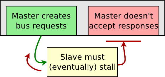 |
The difficult part about these ready signals is backpressure.
If the master holds BREADY low, the slave must know to lower AWREADY and
WREADY. This is also true if the master holds RREADY low, then the slave
needs to know to lower ARREADY. Because these aren’t cases people normally
think of, these signals are easy to get wrong when testing via simulation alone.
It’s just not a case you might think of when writing your simulation scripts.
In general, there’s two ways to deal with the incoming channels–both with and without skid buffers. With skid buffers, your slave will be able to achieve lower latency and higher throughput. Without the skid buffers, your slave will have less logic and only 50% throughput, but it will still be a valid AXI-Lite slave.
In this section, we’ll examine how to handle these handshakes the easy way–without using any skid buffers.
Let’s start with the write side again. We’ll follow (and fix) Xilinx’s
example here
and only raise S_AXI_AWREADY when both S_AXI_AWVALID and S_AXI_WVALID
are true. This will synchronize the two channels together–an important part
of any AXI slave.
A first draft of this logic might look like,
	initial	axil_awready = 1'b0;
	always @(posedge S_AXI_ACLK)
		axil_awready <= (S_AXI_AWVALID && S_AXI_WVALID);
While this might work most of the time, it won’t work all the time.
Indeed, if we were to leave this logic like this, then we’d be making the
same (rough) mistake that Xilinx made with their
core. The problem is that
we didn’t check for backpressure. So, let’s add that check in to our logic,
and make certain that axil_awready is low if ever the output channel
is stalled. That is, we aren’t ready if ever BVALID is high while
BREADY is still low.
	always @(posedge S_AXI_ACLK)
		axil_awready <= (S_AXI_AWVALID && S_AXI_WVALID)
			&& (!S_AXI_BVALID || S_AXI_BREADY);
While this is closer to what we want, we’re still not there.
With this logic alone, it is still possible that axil_awready might be true
on the same cycle that BVALID && !BREADY were also true. (Remember,
axil_awready is registered, and so it has to be set one clock earlier!)
Were axil_awready to ever be true while BVALID && !BREADY, a write
response would get lost and our
bus
would hang–much like
Xilinx’s demo will hang.
Let’s fix this by throttling our writes down to one write every other clock
cycle. We’ll also clear awready following any reset for good measure.
	initial	axil_awready = 1'b0;
	always @(posedge S_AXI_ACLK)
	if (!S_AXI_ARESETN)
		axil_awready <= 1'b0;
	else
		axil_awready <= !axil_awready
			&& (S_AXI_AWVALID && S_AXI_WVALID)
			&& (!S_AXI_BVALID || S_AXI_BREADY);
We can now set both of our write ready signals to be equal to this one, and know that they’ll be properly synchronized.
	assign	S_AXI_AWREADY = axil_awready;
	assign	S_AXI_WREADY  = axil_awready;
Next, in order to match our logic above and to be able to use the same
logic both with and without a
skid buffer,
we’ll rename some of our signals
below–specifically S_AXI_AWADDR, S_AXI_WDATA, and S_AXI_WSTRB.
	assign 	awskd_addr = S_AXI_AWADDR[C_AXI_ADDR_WIDTH-1:ADDRLSB];
	assign	wskd_data  = S_AXI_WDATA;
	assign	wskd_strb  = S_AXI_WSTRB;
Let me back up for a moment and discuss ADDRLSB. This is another one of
those values Xilinx got wrong.
It’s supposed to be equal to the lowest address bit of the word address. So,
for a 32-bit word, this should be bit 2–allowing bits 1:0 to be used to
specify which byte within the word a read is supposed to start from.
AXI supports sub-word
accesses nicely via the AxSIZE signal.
Using that signal, we might be able to tell if a read or write was for 8-bits
(AxSIZE==3'b000) or 16-bits (AxSIZE==3'b001) instead of all 32-bits
(AxSIZE==3'b010). AXI-Lite doesn’t have this signal. Instead, AXI-Lite only
has the WSTRB signal and even that only applies to writes. In other words,
these sub-32-bit address bits really aren’t that useful for us, so we can
simply drop them.
How many bits should be dropped? Given that AXI-Lite is only ever a 32-bit data width, the answer is an easy 2-bits. But what if you wanted a 16-bit data width, or a 64-bit width? Then you might consider writing something like Xilinx tried,
localparam ADDRLSB = (C_AXI_DATA_WIDTH/32)+1;The only problem is that I’ve seen this code copied into
AXI (full) cores. That’s
right, into cores that don’t have a fixed 32-bit width where this calculation
doesn’t match reality. (In one particular example, some one used this
calculation on a 128-bit bus, only to struggle with the fact that his core
only ever wrote every other word …) The correct setting for ADDRLSB
should be,
localparam ADDRLSB = $clog2(C_AXI_DATA_WIDTH)-3;This will then evaluate to 2 for a 32’bit
bus, as we would want.
The address bits above the ADDRLSB bit, bits C_AXI_ADDR_WIDTH-1:ADDRLSB,
can now be used to specify which word we wish to transfer–whether
r0, r1, r2, or r3. These will be the address bits we focus on.
Finally, we need to create a signal to indicate that a value is ready to
be written, axil_write_ready. The easy answer here is to use axil_awready,
the same signal we are using to accept the write request into our core.
This can then be used by all of our write logic above to tell
us when to write a new value to one of our registers.
assign axil_write_ready = axil_awready;Sometime after Vivado 2016.3, Xilinx fixed the write bug in their AXI-Lite demonstration core. (As of this writing, they have yet to fix the read bug.) Their updated core can handle one write every three clocks. You’ll find that logic above is much simpler, and it will even handle one write every two clocks–a nice throughput improvement–as shown in Fig. 5 below.
 |
Simplicity is a good thing.
Reads are even easier to accomplish that writes. In this case, we can just
set S_AXI_ARREADY to be the complement of S_AXI_RVALID. This allows us
to hold S_AXI_ARREADY high until a read request comes in, and then
immediately drop it until the read response has gone out.
	always @(*)
		axil_arready = !S_AXI_RVALID;

	assign	S_AXI_ARREADY = axil_arready;
The neat part about complementing logic like this on a LUT-based architecture, is that the complement can often (not always) be folded into the LUT that would read this signal, and so this becomes a zero cost signal.
You can see how well we can handle reads in Fig. 6 below.
 |
Finally, we’ll read from this IP
core
any time S_AXI_ARVALID && S_AXI_ARREADY
are true, and we’ll read from an address given in S_AXI_ARADDR.
	assign	axil_read_ready = (S_AXI_ARVALID && S_AXI_ARREADY);

	assign	arskd_addr = S_AXI_ARADDR[C_AXI_ADDR_WIDTH-1:ADDRLSB];
That’s about as simple as AXI-Lite logic can be made to be. It’s also only 51 LUTs, vs 69 for Xilinx’s (broken) AXI-Lite demo (adjusted for four registers each).
With Skid Buffers
 |
The problem with the really simple AXI-Lite logic above is simply throughput performance. The most it will ever perform is one transfer every other clock tick. If you want performance from an AXI-Lite core, you’ll want to add skid buffers to your design.
You should also realize, however, that you’ll be fighting an uphill battle. Xilinx’s infrastructure isn’t built for AXI-Lite performance. Just fixing your AXI-Lite core won’t fix their crippling AXI to AXI-Lite bridge, but I still do it as a matter of pride in my own workmanship. That said, there are AXI to AXI-Lite bridges that will preserve the 100% throughput of AXI, and there are AXI-Lite crossbars if these are things you are interested in. You just have to know to where to look for and find them.
 |
A skid buffer is a really simple piece of logic that converts a combinatorial ready signal to a registered one, as shown in Fig. 7 above.
The key to getting high performance from any AXI slave is to place a
skid buffer
on all the incoming channels, AW, W, and R, as shown in Fig. 8 on the
left. As you may recall from our earlier
skid buffer discussion,
this allows the various READY signals generated by
our core
to be registered, even though the ready logic we need is combinatorial.
Here’s how easy this gets. First, place a
skid buffer
on both the AW and W channels. They’ll need to have an appropriate
width for the write address, write data, and write strobes.
	wire	awskd_valid, wskd_valid;

	skidbuffer #(.OPT_OUTREG(0),
			.DW(C_AXI_ADDR_WIDTH-ADDRLSB))
	axilawskid(//
		.i_clk(S_AXI_ACLK), .i_reset(i_reset),
		.i_valid(S_AXI_AWVALID), .o_ready(S_AXI_AWREADY),
		.i_data(S_AXI_AWADDR[C_AXI_ADDR_WIDTH-1:ADDRLSB]),
		.o_valid(awskd_valid), .i_ready(axil_write_ready),
		.o_data(awskd_addr));
Since we have two channels, and two sets of handshaking signals (one for each channel), we’ll need two skid buffers.
	skidbuffer #(.OPT_OUTREG(0),
			.DW(C_AXI_DATA_WIDTH+C_AXI_DATA_WIDTH/8))
	axilwskid(//
		.i_clk(S_AXI_ACLK), .i_reset(i_reset),
		.i_valid(S_AXI_WVALID), .o_ready(S_AXI_WREADY),
		.i_data({ S_AXI_WDATA, S_AXI_WSTRB }),
		.o_valid(wskd_valid), .i_ready(axil_write_ready),
		.o_data({ wskd_data, wskd_strb }));
Then we’ll accept a write request (and unstall the skid buffers above) any time there’s both a write address and write data available. That is, unless the outgoing interface is stalled.
	assign	axil_write_ready = awskd_valid && wskd_valid
			&& (!S_AXI_BVALID || S_AXI_BREADY);
It’s that simple.
Now we can just repeat the process for the read channel. First, we’ll add the skid buffer.
	wire	arskd_valid;

	skidbuffer #(.OPT_OUTREG(0), .DW(C_AXI_ADDR_WIDTH-ADDRLSB))
	axilarskid(//
		.i_clk(S_AXI_ACLK), .i_reset(i_reset),
		.i_valid(S_AXI_ARVALID), .o_ready(S_AXI_ARREADY),
		.i_data(S_AXI_ARADDR[C_AXI_ADDR_WIDTH-1:ADDRLSB]),
		.o_valid(arskd_valid), .i_ready(axil_read_ready),
		.o_data(arskd_addr));
Then we accept a read request any time one is present, and the outgoing
R channel isn’t stalled.
	assign	axil_read_ready = arskd_valid
			&& (!axil_read_valid || S_AXI_RREADY);
Here in this context, the
skid buffers seem like
less work than without. This isn’t quite the case. The reality is instead
that the skid buffers
hide the complexity of the AXI channel signaling within them making things
look simple here. As a result, instead of 51 logic elements, we’ll now be
using closer to 114. It’s still small beans, but it is over twice the size
of what
the core
was before.
How well does this core perform with the skid buffers attached? Check out the write performance in Fig. 9, where 4 write beats are accomplished in 9 clocks periods in spite of three stall clocks and the write data being misaligned by a clock period.
 |
If you look carefully at Fig. 9 above, you’ll notice that certain values
disappear for a time. For example, the A0 (white) value vanished for a
clock period before the white BVALID response was generated. Similarly,
the brown A2 and D2 values vanished while the yellow BVALID output
was stalled. Those values were maintained for us within the
skid buffers–making
sure that we didn’t lose them in spite of the fact that the various
interfaces have stalled.
The read performance, shown in Fig. 10, is also similar in that 4 read requests are returned in 8 clock periods in spite of 3 stall cycles.
 |
The write performance would have been as fast as this read performance, if I had chosen to issue the write address and write data to the core on the same clock cycle–something the master could easily choose to do.
Formal Properties
How about verifying this core?
We’ll, there’s the easy way to make certain we are following AXI-Lite signaling: just connect the formal AXI-Lite property file to your core and be done!
	localparam	F_AXIL_LGDEPTH = 4;
	wire	[F_AXIL_LGDEPTH-1:0]	faxil_rd_outstanding,
					faxil_wr_outstanding,
					faxil_awr_outstanding;

	faxil_slave #(
		.C_AXI_DATA_WIDTH(C_AXI_DATA_WIDTH),
		.C_AXI_ADDR_WIDTH(C_AXI_ADDR_WIDTH),
		.F_LGDEPTH(F_AXIL_LGDEPTH),
		//
		// See the property file for a description of
		// these parameters--what they are, how they work,
		// and what they do.
		//
		.F_AXI_MAXWAIT(2),
		.F_AXI_MAXDELAY(2),
		.F_AXI_MAXRSTALL(3),
		.F_OPT_COVER_BURST(4)
	) faxil(
		.i_clk(S_AXI_ACLK), .i_axi_reset_n(S_AXI_ARESETN),
		//
		.i_axi_awvalid(S_AXI_AWVALID),
		.i_axi_awready(S_AXI_AWREADY),
		.i_axi_awaddr( S_AXI_AWADDR),
		.i_axi_awcache(4'h0),
		.i_axi_awprot( S_AXI_AWPROT),
		//
		.i_axi_wvalid(S_AXI_WVALID),
		.i_axi_wready(S_AXI_WREADY),
		.i_axi_wdata( S_AXI_WDATA),
		.i_axi_wstrb( S_AXI_WSTRB),
		//
		.i_axi_bvalid(S_AXI_BVALID),
		.i_axi_bready(S_AXI_BREADY),
		.i_axi_bresp( S_AXI_BRESP),
		//
		.i_axi_arvalid(S_AXI_ARVALID),
		.i_axi_arready(S_AXI_ARREADY),
		.i_axi_araddr( S_AXI_ARADDR),
		.i_axi_arcache(4'h0),
		.i_axi_arprot( S_AXI_ARPROT),
		//
		.i_axi_rvalid(S_AXI_RVALID),
		.i_axi_rready(S_AXI_RREADY),
		.i_axi_rdata( S_AXI_RDATA),
		.i_axi_rresp( S_AXI_RRESP),
		//
		.f_axi_rd_outstanding(faxil_rd_outstanding),
		.f_axi_wr_outstanding(faxil_wr_outstanding),
		.f_axi_awr_outstanding(faxil_awr_outstanding)
		);
You should now be able to pass a bounded model check of any length.
How about an unbounded model check?
In this case, all we need to do is to correlate the three counters,
1) the number of write address requests outstanding, faxil_awr_outstanding,
2) the number of write data requests outstanding, faxil_wr_outstanding, and
3) the number of read requests outstanding, faxil_rd_outstanding,
against what our logic expects.
For example, if we aren’t using the
skid buffers,
there should never be more than one item outstanding. (We don’t have storage
for more …) Not only that, but any time BVALID is true there should be
exactly one write address or write data item outstanding. The same is true
for RVALID, making the proof easy.
	always @(*)
	if (!OPT_SKIDBUFFER)
	begin
		assert(faxil_wr_outstanding == (S_AXI_BVALID ? 1:0));
		assert(faxil_awr_outstanding == faxil_wr_outstanding);

		assert(faxil_rd_outstanding == (S_AXI_RVALID ? 1:0));
The proof is a bit harder for the
skid buffer
case. In this case, we need to count what’s in the
skid buffer
against our number of counts. Hence, if the
skid buffer
ever drops the outgoing ready signal, then there’s an item sitting in the
skid buffer
waiting to be accepted by
our core.
(Feel free to check out Figs. 9 and 10 above to see this in action.)
We can count these extra items with something like
(S_AXI_AWREADY ? 0:1)–knowing that AWREADY will only ever be low if
there’s something in the buffer. Other than that change,
the counter checks should look the same.
	end else begin
		assert(faxil_awr_outstanding== (S_AXI_BVALID ? 1:0)
			+(S_AXI_AWREADY ? 0:1));
		assert(faxil_wr_outstanding == (S_AXI_BVALID ? 1:0)
			+(S_AXI_WREADY ? 0:1));

		assert(faxil_rd_outstanding == (S_AXI_RVALID ? 1:0)
			+(S_AXI_ARREADY ? 0:1));
	end
At this point, we’ve proven that the bus works. We haven’t really proven that our core works, so you might want to consider adding some logic to check that the design actually reads from your registers as you might like.
	always @(posedge S_AXI_ACLK)
	if (f_past_valid && $past(S_AXI_ARESETN && axil_read_ready))
	begin
		assert(S_AXI_RVALID);
		case($past(arskd_addr))
		0: assert(S_AXI_RDATA == $past(r0));
		1: assert(S_AXI_RDATA == $past(r1));
		2: assert(S_AXI_RDATA == $past(r2));
		3: assert(S_AXI_RDATA == $past(r3));
		endcase
	end
Finally, there’s one last check. That is, we wanted to make certain that
RDATA was zero if there was nothing to return–but only if OPT_LOWPOWER
was set. This is easily checked and verified.
	always @(*)
	if (OPT_LOWPOWER && !S_AXI_RVALID)
		assert(S_AXI_RDATA == 0);
I’ve put the whole proof together into five
parts:
Two verify that the AXI-lite signaling is handled properly first without
and then with the
skid buffer.
The next two double check that we can actually write four values to
the core,
and read four values from it–letting the solver pick
which four values. This was the purpose of the F_OPT_COVER_BURST option
above–specifying that we wanted to be able to check how fast four
values might be returned. The last part checks OPT_LOWPOWER.
Conclusion
It’s unfortunate that the vendor AXI-Lite examples are so broken, because building and verifying that this slave was protocol compliant wasn’t really all that hard to do. The trickiest parts involved handling any potential backpressure and guaranteeing that all outgoing signals were properly registered.
I realize I haven’t really used all of the AXI-Lite
signals in
this example.
For example, we haven’t used the low order address bits nor wave we used the
various AxPROT signals. The reason why not is simply because we didn’t
need to. Indeed, there’s a strong argument to be made that AXI is way more
complicated than it needs to
be–but
we can leave that discussion for another day.
Until then, feel free to modify this core for your own purposes. Don’t forget to check out how easy it is to formally verify that it works along the way.
Lo, this only have I found, that God hath made man upright; but they have sought out many inventions. (Eccl 7:29)