
Rethinking Video with AXI video streams
So far on this blog, I’ve really only shared one video article. This article discussed how to generate the frame synchronization signals sufficient to drive a VGA controller. It also demonstrated a video simulation capability that has been very useful to me when working with video.
Since then, I’ve had the opportunity to build several new video modules. These include an AXI video capture device (frame grabber), an AXI frame buffer, an empty AXI video source, an AXI stream sprite module, and even a (not yet tested) overlay module to overlay one AXI video stream on top of another. More recently, I’ve expanded this work with a data plotting capability, a histogram capture and plot capability, and (once its tested and works) a waterfall display for a spectrogram. Should the Lord will, I’d also like to demonstrate a half-spectrogram/half-waterfall display, but that one has (yet) to be implemented. (It shouldn’t be too hard to make, given my FFT and the components above …)
Along the way, I’ve learned a lot, and thought I might write to share some of these lessons.
Before diving in, however, I’d like to mention Will Green’s FPGA Graphics blogs. He discusses not only the graphics sync timing, but goes on to discuss pong, sprites, star fields, frame buffers, lines, triangles, arbitrary 2D shapes and animations. I’ve read several of these posts, and would love to commend them to you here. Indeed, I expect I’ll be digging even deeper into some of his blogs, to see how he accomplishes his various tasks.
Will Green’s graphics blog series, however, follows the form of much of my earlier graphics work. Since then I’ve come across AXI handshaking, and realized it solves a lot of the problems I’ve had with video in the past.
Let’s start, therefore, with some of the problems I’ve struggled with. We’ll move from there to discuss the AXI video stream protocol, and then some formal properties you can use when working with video to get things going properly.
Video Problems
 |
When I last demonstrated and discussed
video, I used three global
signals for pipeline control: Read, Newline, and NewFrame. Together, they
generated a rough “global-CE” pipeline control
mechanism
Using these three signals, I was able to generate and demonstrate a proper
frame buffer,
which could draw an arbitrary image to a screen–even in simulation.
(See Fig. 1) Of these three signals, the read signal was not all that unlike
Will Green’s de, or “data enable” signal as
he calls it. Indeed, they were both “global-CE” pipeline control
signals.
The biggest difference was that my VGA outputs were registered, vs. his
were combinatorial outputs. (Not a big difference, unless you see a
performance impact.) When my read signal was high, the low level graphics
driver was reading a pixel from its environment. When his de signal is
high, the low level graphics driver is producing a pixel to the VGA port.
Unfortunately, those three signals proved insufficient for my needs, and much of my personal video development stagnated for a while as a result.
Why was that?
Well, basically, there are several challenges associated with building video that aren’t necessarily present in other types of RTL design.
 |
These challenges are outlined in Fig. 2. We’ll discuss them briefly here.
The first problem is that a full size, full colour, frame buffer will not (often) fit into memory. Will Green manages to make his frame buffer fit in RAM fit by restricting his video to 640x480, and his color to a single bit. This won’t work if you want full color, or a 1920x1280 resolution–unless you have a lot of block RAM on an expensive chip. (Even then, you’d have better things to use it on.)
This will force you off chip, and generally into an external SDRAM of some type. This results in two consequences. First, the SDRAM will have a specific clock frequency that it will want to run at. While this clock frequency may match your pixel clock rate, that would be an unlikely but lucky break. More often, the two rates will be different–especially since SDRAM’s don’t support the wide range of pixel clock rates required by a robust video solution. This will force you to use an asynchronous FIFO somewhere in your design to move from the one clock rate to another.
 |
The second consequence of going off chip is that you’ll need a bus protocol of some type. AXI, AXI-lite, and Wishbone are all common bus protocols which could work well for this purpose. Why do you need a bus protocol? First, because of contention for the device. Specifically, you’ll want to be able to both adjust that memory and to use it for other purposes. Second, it will allow you to split your project’s development at a natural seam–allowing you to use an SDRAM driver built by someone else–such as Xilinx’s memory interface generator (MIG). To make matters worse, bus timing and latency aren’t necessarily predictable: your latency will depend on whether or not something else is using the bus at the same time. This means that you’ll want to use high speed burst accesses to read/write video memory–getting on and off the bus as fast as possible.
Along the way, it doesn’t help that in many video processing applications, the submodules have no control of the pixel clock rate, mode, or reset. A video source may change video modes, clock rate, height and width, at any time the user presses a button up stream. Everything downstream must just “still work” under such eventualities. Further, the CPU might reset the processing chain at any time. Again, things need to “just work”.
The next problem with the global-CE approach to video signals is, how shall you deal with signals that require multiple processing steps? For example, what if you wish to place a sprite on the video stream, but that sprite has more than one bit of alpha? The resulting pixel should have a value of:
	output_red   = input_red   * (1-alpha) + sprite_red   * alpha;
	output_green = input_green * (1-alpha) + sprite_green * alpha;
	output_blue  = input_blue  * (1-alpha) + sprite_blue  * alpha;
This is likely to cost you a clock or two to calculate. (I used two in my implementation.) This would be in addition to the clock required to look the sprite’s value up from sprite memory.
In other words, while you can make video work with the single enable signal approach, doing so will only get you so far before you’ll run into some challenges that are more difficult to deal with. Further, as we’ll see, the components you will need to make it work tend not to be very portable.
For all of these reasons, I’ve found the AXI Stream protocol to be a viable alternative for moving video streams around within a design.
AXI Stream Video
We’ve discussed the AXI stream protocol several times on this blog. It’s a broadly applicable protocol for moving data around on chip, albeit leaving the developer with some challenges.
One advantage of AXI stream is the handshaking protocol. Basically a “source” (master) will set the VALID flag whenever it has data (i.e. one or more pixels) available, and the “destination” (slave) will set the READY flag when it is ready and able to receive data.
As we’ve discussed before, there are two problems with this protocol: what happens when the master produces data faster than the slave can accept it, and what happens when the slave wants more data than the master can produce? When it comes to video, this question is solved (in general) by the component holding the clock source. There are two possibilities here: the source video can drive the clock, or the FPGA can generate a clock to drive video.
If the timing source is an external video source signal, such as might be produced by a camera or other video output device, then that device controls the timing as shown in Fig. 4 below.
 |
This can easily be accomplished using the AXI stream TVALID signal, but only
as long as TREADY can be guaranteed high whenever TVALID is produced
by the AXI stream to video source
converter.
This becomes our first criteria of success: the
back pressure
can never be allowed to build up so much that the source data has nowhere to
go. Where we to implement an AXI ABORT
signal,
this is where it would be generated.
 |
The other possibility, shown in Fig. 5 above, is that the pixel clock would be
generated internally within the FPGA, and thus the final converter–from AXI
stream to VGA
(HDMI, or … whatever)–would control timing via the TREADY signal. In
this case, the processing chain must guarantee that TVALID will be true
whenever this final TREADY is high.
I’ll come back and discuss synchronization some more in a moment.
For now, let me point out that video requires two other signals: TLAST and
TUSER, as shown in Fig. 6 on the left.
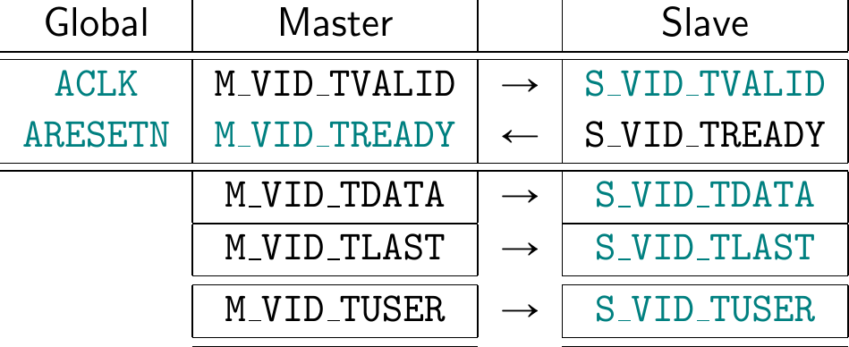 |
According to Xilinx’s AXI4-Stream Video IP and System Design
Guide,
the TLAST signal will be set on the last beat of any horizontal line–as an
“End-of-Line” (EOL) indication, whereas TUSER will be set on the first beat
of any frame as a “Start-of-Frame” (SOF) indication.
 |
I’m sure that I’m not the first person to say this, but doesn’t that seem
backwards to you? I mean, in every other AXI stream application protocol
I’ve seen, the beat following TLAST will be the beginning of a “new-packet”.
You can therefore use TLAST to synchronize the entire protocol on that new
packet. Even better, because TLAST takes place one cycle before the new
packet starts, you can use it as a reset signal if necessary–to reset any
packet processing counters to be ready for the next frame. Likewise, if you
have a stream to memory copy ending at the end of a packet, shouldn’t that
copy end with the one and only TLAST?
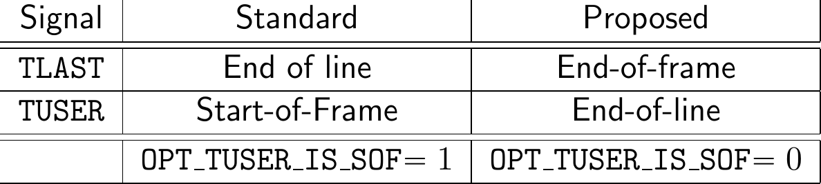
Let me therefore propose instead that TLAST should be set to the last pixel
in a frame, not the last pixel in a line. This would make TLAST an
“End-of-Frame” (EOF) indication.
For comparison, Fig. 8 shows the difference of which pixel would be marked with the “start-of-frame” (SOF) marker vs the “end-of-frame” (EOF) marker that I would propose.
 |
Unfortunately, standards once built tend to last for a long, long
time. The
AXI video stream standard may well be one of those standards at this time.
It’s for this reason that I’ve been building my IP to both rules: the standard,
and what I think should be the standard. As a result, you’ll often find an
OPT_TUSER_IS_SOF parameter within my video IPs. When set, the IP will
interpret the TUSER signal as a start of frame signal, and when clear it
will interpret TUSER as a horizontal EOL signal–as shown in Fig. 7 above.
This leaves one more issue to deal with when dealing with video: how should the reset be handled? As mentioned in Fig. 2 above, the video processing chain may be reset separate from the global reset. Worse, the video pixel clock may be dropped at any time. So … how shall this be dealt with?
This leads to my next criteria of AXI video stream processing: Any video processing component must be able to handle partial frames, and resynchronize on the SOF (or EOF) marker independent of any reset which may (or may not) be properly present.
Let’s summarize these AXI stream video rules, shall we?
-
Sources must generate TUSER/TLAST signals based upon the original synchronization signals embedded in the source signals. Any mode parameters required (porch size, etc.) should be determined at runtime if possible.
Changing modes aren’t necessarily an error, although any mode changes should be reported to the user.
The important rule here is that sources should generate an error for the user whenever they detect any back pressure they cannot handle. (Mine doesn’t do this yet, but it will be a simple enough upgrade.)
-
Processing components should resynchronize everything on every
SOF/EOFsignal, whether or not it appears when it is expected or not. -
Memory writing components, such as frame grabbers, should guarantee that they do not write beyond the end of any allocated memory–regardless of how they are (or are not) synchronized.
-
Sinks must either:
-
Generate their own
TUSER/TLASTsignals, and lock the incoming stream to them. In my designs, if an out of sync condition is ever detected,TREADYis held high untilTVALID && TLAST(i.e.TVALID && EOF). It’s then lowered until the sink is ready for the new frame’s data. If done well, the sink will always generate a reliable video signal even if an upstream component misbehaves.In this case, the sink should generate an error if the incoming pixel stream ever runs dry, such that
TREADY && !TVALID. -
Lock to the
TUSER/TLASTsignals provided by the upstream source.In this case, the sink should also generate a notice to the system if a resync is ever required. Sometimes I’ll handle this via a “glitch counter”. Once the glitch counter stops incrementing, you know the system has properly synchronized.
This leads to a processing system requirement that all processing components must be able to process at least one more pixel per line than the protocol requires (ideally more), in order to allow the processing component to catch up with and thus synchronize with the sink.
-
Using these rules, we can now come back in a later post and build some AXI video stream components.
Formal Video Properties
What would a ZipCPU article be without discussing formal verification? So, before we leave let’s build a quick set of video interface properties. As you may recall, I think of formal interface files as if they were gold. Why? Because a good formal interface property set can 1) verify both ends of any link, 2) be re-used over and over, and 3) it can form a basis for the beginning of any formal proof. That is, if you have no other ideas of what to put in your proof, you can always start with the interfaces.
So, let’s do that today.
Better yet, this property set isn’t going to be all that complicated. If you’ll remember, video (in general) is nothing more than a pair of counters.
So, let’s quickly build an AXI Stream Video interface property set before closing.
We’ll parameterize this file by the number of bits per pixel, the number of
bits required to represent a screen position, and whether or not TUSER is
being used as a SOF signal vs an EOL signal.
module	faxivideo #(
		parameter	PW = 24,		// Bits per pixel
		parameter	LGDIM = 10,
		parameter [0:0]	OPT_TUSER_IS_SOF = 1
	) (
		input	wire			i_clk, i_reset_n,
		//
		input	wire			S_VID_TVALID,
		input	wire			S_VID_TREADY,
		input	wire [PW-1:0]		S_VID_TDATA,
		input	wire			S_VID_TLAST,
		input	wire			S_VID_TUSER,
		//
		input	wire [LGDIM-1:0]	i_width, i_height,
		output	reg	[LGDIM-1:0]	o_xpos, o_ypos,
		output	reg			f_known_height,
		output	wire			o_hlast, o_vlast, o_sof
	);
Our property set will accept as an input all the wires associated with an AXI video stream. We’ll also accept the height and width of the frame as inputs. These can either be known by your design, or arbitrary “anyconst” values. For example, you could set up a pair of values within the formal property section of any component, such as:
	// Anyconst value example (not part of the formal video property set)
	(* anyconst *)	reg	[LGDIM-1:0]	f_width, f_height;
These values could then be passed to the interface property set as the “true” height and width of the video channel–even if your design doesn’t know these values yet.
Our first properties will be those of the basic AXI Stream. These come in two parts. First, VALID should be low following any reset.
	always @(posedge i_clk)
	if (!f_past_valid || !i_reset_n)
	begin
		// We should work regardless of whether a user uses a reset
		// or not, and regardless of whether or not it is asynchronous.
		// Hence ... no property here--we'll catch it on the next clock
		// cycle.
	end else if ($past(!i_reset_n))
	begin
		assert(!S_VID_TVALID);
Second, in the event of any back
pressure,
the TDATA, TLAST, and TUSER signals should be held constant.
	end else if ($past(S_VID_TVALID && !S_VID_TREADY))
	begin
		assert(S_VID_TVALID);
		assert($stable(S_VID_TDATA));
		assert($stable(S_VID_TLAST));
		assert($stable(S_VID_TUSER));
	end
Note that this wouldn’t really apply to a video source, since buffer space is limited–as I mentioned above. But we’ll pretend it applies uniformly either way.
These assertions might also violate my rule of only making assertions about outputs and any internal signals, should you wish to apply this to an AXI stream coming into an IP. In that case, you’ll need to either modify these to turn them into assumptions, or create another set of assumptions within your IP to match these.
Once we know that the stream is a proper AXI stream, we can then calculate the current position of the pixel within that stream. These position values may then be used by the IP instantiating the property set, or not. Your call.
On any reset, the position resets to zero–i.e. to the top left of the screen.
	initial	o_xpos = 0;
	initial	o_ypos = 0;
	initial	f_known_height = 0;
	always @(posedge i_clk)
	if (!i_reset_n)
	begin
		o_xpos <= 0;
		o_ypos <= 0;
		f_known_height <= 0;
Then, on any new pixel, the video signals advance. The horizontal position will advance from left to right up to the end of the line, and then it will be reset back to the beginning of the line–the left side. The vertical position will also advance from the top downward, although only at the end of every line, up until the full height of the screen before getting reset.
	end else if (S_VID_TVALID && S_VID_TREADY)
	begin
		// Advance the horizontal X position, from left to right
		if (o_xpos + 1 == i_width)
			o_xpos <= 0;
		else
			o_xpos <= o_xpos + 1;

		if (o_xpos + 1 == i_width)
		begin
			// New line.  Advance the vertical Y position, from
			// top to bottom
			if (o_ypos + 1 == i_height)
			begin
				o_ypos <= 0;
				f_known_height <= 1;
			end else
				o_ypos <= o_ypos + 1;
		end
	end
Remember when I said video is just a pair of counters? Here you can see the two counters for an AXI video stream. The cool thing is that you can now use these two counters to verify the logic within your IP.
There is one new piece to these counters: f_known_height. I use this to
verify an IP that needs to discover the height of the incoming frame. Once
the first frame has passed, that is once the EOF has been received,
the height can now be known. This can then be used with an assertion that
any recovered video height has the correct value.
From here, I can generate three more signals: HLAST (EOL), VLAST (last
line), and SOF (start of frame). Once you have the screen position, together
with the width and height of the screen, these signals become easy to define.
	assign	o_hlast = (o_xpos == i_width  - 1);
	assign	o_vlast = (o_ypos == i_height - 1);
	assign	o_sof   = (o_xpos == 0 && o_ypos == 0);
Further, we’ll want to make certain any incoming height or width are reasonable. The minimum video size, at least for this property set, is a 3x3 window. (Small sizes are good, especially if they can be used to make formal proofs run faster …) In general, the video size should be held constant–although we’ll allow it to change during any reset.
	always @(posedge i_clk)
	if (f_past_valid && $past(i_reset_n) && i_reset_n)
	begin
		assume($stable(i_width));
		assume($stable(i_height));

		if (!o_sof || S_VID_TVALID)
		begin
			assume(i_width  > 2);
			assume(i_height > 2);
		end
	end
No, this isn’t quite as robust as my “rules” for video processing above. If you’ll remember, I argued above that video components needing height or width would need to derive them and re-derive them if they ever changed. This assumption guarantees they’ll never change outside of a reset, so the properties might leave you blind in that eventuality. That won’t stop you from building a good design, but it might keep the tool from catching any bugs within it–depending on how you use these values.
Now that we know our position on the screen, we can run a quick check to make sure our formal output counters match the actual height and width of the display as they are given to us.
	always @(posedge i_clk)
	if (f_past_valid && $past(i_reset_n) && i_reset_n)
	begin
		assert(o_xpos < i_width);
		assert(o_ypos < i_height);
	end
That leaves us only two more signals to verify: TLAST and TUSER.
How we verify these will depend upon whether we are requiring TUSER to
represent the start of frame, or TLAST representing the end of the frame.
Both will work–depending on the OPT_TUSER_IS_SOF parameter.
	always @(posedge i_clk)
	if (f_past_valid && i_reset_n && $past(i_reset_n) && S_VID_TVALID)
	begin
		if (OPT_TUSER_IS_SOF)
		begin
			assert(S_VID_TLAST == o_hlast);
			assert(!f_known_height || S_VID_TUSER == o_sof);
If TUSER represents the start of the frame, then it should match the o_sof
signal and TLAST should match our end-of-line signal o_hlast. You might
notice that I have made an exception here to the TUSER rule. That’s to allow
conversions between the two protocols. In other words, an initial frame can
have its lines counted before needing to set TUSER.
Reading this over now, I should note that Xilinx’s
guide
would require that no pixels should be output prior to the first SOF. I
have yet to enforce this rule within my designs. Enforcing it here would
simply mean dropping the f_known_height requirement from this assertion.
Returning back to OPT_TUSER_IS_SOF, if TUSER is not a start of frame
signal, then (in my version of the AXI video stream protocol)
we’ll assert that TLAST is the end of frame signal and TUSER the end of
line signal.
		end else begin
			assert(S_VID_TLAST == (o_vlast && o_hlast));
			assert(S_VID_TUSER == o_hlast);
		end
	end

endmodule
No, there’s not much more to this property set. There doesn’t need to be. Your design might need more properties, but at least this will give you some starting ones to work with.
Conclusions
The more I’ve been working with AXI video streams, the more I’ve enjoyed using
the AXI stream video protocol. It’s much more versatile than my own
protocol,
and the back pressure
feature solves the problem of how to synchronize multiple components in a
pipeline together nicely. Even better, by pushing the stream signals,
TLAST and TUSER, through the pipeline from the source, we solve the
problems associated with generating these signals at the end of the pipeline
where they quickly get out of sync.
Now with this background, I should be able to come back and discuss how to build a hardware sprite capability. Lord willing, that can be the next article in this series.
For a just man falleth seven times, and riseth up again: but the wicked shall fall into mischief. (Prov 24:16)