
Formally verifying register handling
Symbiotic EDA has a fascinating product called MCY: Mutation coverage with Yosys. The idea behind MCY is that it will subtly change (mutate) your design to then see if your test bench can catch the changes. The goal is to measure, not how good your design is, but rather how complete your test bench is.
I’ve now tried MCY on a couple of my designs. I’ve tried it on the ZipCPU, and I’ve tried it on the Easy AXI-lite slave we built together on the blog. In both cases, it worked as advertised, yet left me a little bit unsettled by what my test benches weren’t checking for.
In the case of the ZipCPU, I already knew that my test bench was flawed: I’d long since abandoned it for serious testing in favor of formal methods. Sure enough, MCY found holes in my test bench–primarily in the fact that just running a program on the ZipCPU from simulation never checked the debugging interface. Even the test bench that did check the debugging interface never checked that registers within the CPU could be read or written to via the same debugging interface.
Shame on me. That should’ve been a part of my test bench.
The Easy AXI-lite slave made for another valuable test. In this case, I had built a very quick Verilator-based simulation test bench for it to test it against. MCY gave this test bench a coverage number of only 60% or so, meaning that my Verilator based test bench could only find 60% of the mutations.
What did I miss?
-
My simulation never checked whether or not the byte enables were handled properly. This follows from the fact that my test bench only ever checked reading from and writing to entire words.
-
The simulation never checked whether or not the design could handle back-pressure on the AXI bus.
This is a sad reality of simulations. Why check for proper back-pressure handling if you know, whenever you issue a request, that you’ll want to get a response from that request?
I find roughly 1-2 help requests per week on Xilinx’s forums are due to individuals using one of Xilinx’s broken AXI demonstration cores. As you may recall, these cores were primarily broken because they didn’t properly handle back-pressure. Because simulations never checked for this, and their AXI VIP never generated back-pressure, users are often left with a false sense of security that their design works when the opposite is the case.
When I reconfigured MCY to check the formal proof of my Easy AXI-lite design (EASYAXIL), coverage then went up to 79%. Wait, only 79%? Isn’t formal verification supposed to be comprehensive? Isn’t it supposed to be exhaustive? What happened?
What happened was that I had set up my formal proof to check for bus protocol violations. I never checked whether or not the values returned by the bus were the right ones. In other words, of the four checks required for any formal sign off, I had only checked three.
Since then, I’ve had many opportunities to build simple bus slaves, and this lesson has left me knowing that my simulations and formal proofs were often incomplete. This has left me feeling exposed and vulnerable, and so today I’d like to correct that lack. Let’s take a look, therefore, at a simple property set we can add to our design to make certain that any registers within it behave as desired.
First, however, lets back up and look at what I was able to learn from MCY.
MCY Results
MCY requires a bit of setup to get it up and running. Sadly, that setup is often different from one simulator to the next. It’s complicated enough that I’m not going to go into all the details here. If you wan to see how I did it, feel free to check out my setup here.
One of my frustrations with this setup is that I was unable to use my design as it was written. Normally, I build a design and write formal properties into the design at the bottom of the file. Why? Because passing induction requires making assertions about the state of the design across register states. This leads to a white box testing approach, rather than the more traditional black box testing approach. Keeping the properties together with the design seems to facilitate that for me.
The problem with leaving properties at the bottom of the design is that the mutation engine might mutate the properties, and not just the logic. To make this work, the two must be separated. This forced me to create a separate property file to encapsulate the properties required to verify my design, and then to bind it to the design. Access to the SVA bind capability currently requires the commercial version of SymbiYosys.
Still, once set up, I could initialize MCY and apply it to my design. Here, for example, are the results from applying my Verilator-based simulation test alone.
% mcy init
% mcy run -j 6
# ... Lots of outputs ...
Database contains 2000 cached results.
Database contains 979 cached "FAIL" results for "test_eq".
Database contains 21 cached "PASS" results for "test_eq".
Database contains 634 cached "FAIL" results for "test_sim".
Database contains 366 cached "PASS" results for "test_sim".
Tagged 627 mutations as "COVERED".
Tagged 7 mutations as "EQGAP".
Tagged 14 mutations as "NOCHANGE".
Tagged 352 mutations as "UNCOVERED".
Found 7 mutations exposing a formal equivalence gap!
Coverage: 64.04%
This tells us that, without formal verification, of the 1000 mutations that were applied to this design, 634 were were caught by the simulation check. That’s a good thing, though I would like this number to be higher. However, it might be that a change may have been made to the design that doesn’t affect any of its outputs. In order to check for this possibility, I applied an equivalence check to the two designs. If this check finds the mutated design equivalent to the non-mutated design, after searching through (in this case) 15 time steps then the difference might be irrelevant–so we’ll call it “NOCHANGE”. Of all of the mutations, there were only 21 of 1000 times where the equivalence check couldn’t find any difference in performance as a result of the mutation. Of those 21 times, the simulation caught the mutation 7 of those times–showing that our equivalence check couldn’t quite catch all the changes.
In general, though, my simulation test bench only caught 64% of all of the mutations. That’s not a great number. That means 36% of the time a bug might get past my simulation.
Let’s see if we can improve upon this number by adding formal verification into the mix. Here you can see the end of the output below.
Database contains 2359 cached results.
Database contains 981 cached "FAIL" results for "test_eq".
Database contains 19 cached "PASS" results for "test_eq".
Database contains 143 cached "FAIL" results for "test_fm".
Database contains 216 cached "PASS" results for "test_fm".
Database contains 641 cached "FAIL" results for "test_sim".
Database contains 359 cached "PASS" results for "test_sim".
Tagged 777 mutations as "COVERED".
Tagged 7 mutations as "EQGAP".
Tagged 143 mutations as "FMONLY".
Tagged 12 mutations as "NOCHANGE".
Tagged 204 mutations as "UNCOVERED".
Found 7 mutations exposing a formal equivalence gap!
Coverage: 79.20%
In this case, we applied our formal check to only those mutations that didn’t pass the simulation test. Here we find that 641 mutations of the total 1000 were caught by simulation, and of those 359 tests that were missed, another 143 were caught by formal verification using the properties we developed before.
The problem is that this number should be much higher. Formal methods
should’ve caught everything. They didn’t, however, because we never checked
the return data from the design (S_AXI_RDATA)–we only checked that there
was an output value, not that it was the right one.
For that, we’re going to add register checking to our test. This time, our coverage goes up to 99.9%.
Database contains 2386 cached results.
Database contains 981 cached "FAIL" results for "test_eq".
Database contains 19 cached "PASS" results for "test_eq".
Database contains 373 cached "FAIL" results for "test_fm".
Database contains 13 cached "PASS" results for "test_fm".
Database contains 614 cached "FAIL" results for "test_sim".
Database contains 386 cached "PASS" results for "test_sim".
Tagged 980 mutations as "COVERED".
Tagged 7 mutations as "EQGAP".
Tagged 373 mutations as "FMONLY".
Tagged 12 mutations as "NOCHANGE".
Tagged 1 mutations as "UNCOVERED".
Found 7 mutations exposing a formal equivalence gap!
Coverage: 99.90%
That means that 99.9% of all mutations were (now) properly found by either our simulation check, or the updated formal properties for this core.
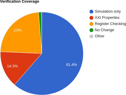 |
Let’s plot out these numbers in Fig. 1, and then go back them to see if we can get a feel for what’s going on. First, of the 1000 mutation checks, 614 of them, or 61.4%, were caught by simulation alone. (This is really backwards, as my first step to verifying a core is typically a formal verification check, not simulation check, but running simulation first was how I was shown to set up MCY.) Of the 386 times where simulation didn’t find the mutation, a formal property check was applied to the design. In 373 of those cases, the formal property check found the mutation leaving 13 cases were neither formal nor simulation were able to find the mutation. Twelve of those cases involved a design that didn’t fundamentally change, whereas the last one was a protocol valid design that was just … different from the original. The difference? The mutated design took an extra clock to return the result. Since it was valid, from a protocol standpoint, it passed the formal check. Since the mutated design wasn’t externally equivalent to the original, MCY flagged this as an “UNCOVERED” mutation above.
That explains the blue, “Simulation only”, region and the green “No change” region in Fig. 1 above. However, the register checking and AXI property regions–while adding up to 373, are only approximately supported by the data above. Sadly, I violated several principles of data handling to plot the differences between these two sets, so let me at least explain what I did: The second test showed that 641/1000 mutations were found via simulation, and an additional 143/1000 were found via simulation alone. If we accept that a rough 143 mutations chosen in the third test therefore would’ve been found using formal methods with AXI properties alone–you might come up with 143/1000 or 14.3% additional coverage via using formal properties. Sadly, this isn’t truly an apples to apples comparison, since the second and third runs of MCY were based upon two separate sets of mutations and I’m now comparing statistics drawn from one sample set to those of another. Therefore, let me only say that these percentages are somewhat approximate–since they will change from run to run as the mutation engine randomly picks different design mutations.
So for the rest of this article, I’d like to look at what it took to get this design from a formal proof that only verified 79% of its functionality (run #2) to one that gets to the 99.9% shown in Fig. 1. The difference was a contract check that I used to verify the various internal register values.
Register Checking
Let me start by addressing the question of “what is a register”, followed by my approach to register checking.
 |
Many designs have multiple registers within them that can be controlled from an external bus by writing to or reading from some address in the design’s memory map. A classic example would be a GPIO device, such as the one shown in Fig. 2. Such a device might simply control the outgoing voltage on a series of output wires. If you set a particular bit in a GPIO register to a ‘1’, the wire controlled by that register might emit a positive voltage on the external output pin, whereas if the bit were set to ‘0’ the wire is held at ground.
 |
Register uses go well beyond simple GPIO peripherals. Indeed, most if not all of the peripherals and controllers I’ve built have some form of register control to them. In the case of my DMA engines, shown in Fig. 3, the transfer length, source and destination addresses are all configured via a bus-accessible register. For my UART, the baud rate can be configured via the bus. For the countdown timer? The time duration. The interrupt controller? Which interrupts are enabled and which are cleared. The QSPI flash controller? Which mode the controller is currently operating within. How about the Wishbone scope? The delay from trigger to the end of the capture. The list goes on. Indeed, it might seem that every RTL controller I’ve built has some amount of registers within it.
 |
Today, we’re going to focus on modifying the EASYAXIL design to add formal register checking to the formal properties checking this design. This way, if any future modification breaks the design later on, the properties will be able to quickly catch the change.
Here’s how we’ll do it: we’ll create a formal register checking module, and then we’ll attach this module to each of the four registers internal to this design to make certain that those registers can each be both read from and written to.
Let’s look through how we might build such a module.
If we want to verify that our register gets written to or read from on
any bus access to a given address, then the first step will be to configure
our check for the right address. That means we’ll need to configure this
formal register property set
with an address, ADDR, that is AW bits wide,
module	faxil_register #(
		parameter		AW = 4,
		parameter [AW-1:0]	ADDR = 0,
and for a bus of some data width, DW.
parameter DW = 32,Not all registers can be fully written to. For example, if you write to the
configuration register in my QSPI
controller,
then the bottom eight bits might get sent out the QSPI port, while bits [11:8]
can be read and written like a (normal) register.
The Wishbone
scope
is similar: the bottom 20 bits control the holdoff from the
trigger, whereas the top
4 bits are status bits returned by the design. To
know which bits should be checked for a generic read/write capability, we’ll
need a MASK parameter. Under this scheme, for every MASK[BIT] that is
set, the bit numbered BIT will be checked to see if it can be read and
written from the bus.
parameter [DW-1:0] MASK = -1,.
As a final parameter, some designs require asynchronous resets. While I don’t normally use them, some contexts require them. Therefore we’ll make an option for asynchronous reset handling, and come back to this again later.
parameter [0:0] OPT_ASYNC_RESET = 1'b0.
That’s the first step, knowing how to configure the property checker for our register.
The next step will be to keep a local copy of the register within the formal register property set.
reg [DW-1:0] f_reg;Now, any time the register we are checking is written to, we’ll keep track of
it’s value in our local copy, f_reg. To do this, I’ve slightly simplified the
interface slightly from the AXI-lite protocol. Specifically, I’ve created an
S_AXIL_AWW port with a (rough) equivalence to
S_AXIL_AWVALID && S_AXIL_AWREADY and S_AXIL_WVALID && S_AXIL_WREADY–since
this is our rule for writing to the register in the first place. If
therefore S_AXIL_AWW is true and the requested address matches the
address of our register, then we’ll update the various bytes in f_reg
as requested by the bus.
	localparam	AXILLSB = $clog2(DW/8);

	always @(posedge S_AXI_ACLK)
	if (S_AXIL_AWW
		&& S_AXIL_AWADDR[AW-1:AXILLSB] == ADDR[AW-1:AXILLSB])
	begin
		for(ik=0; ik < DW/8; ik=ik+1)
		if (S_AXIL_WSTRB[ik])
			f_reg[ik*8 +: 8] <= S_AXIL_WDATA[ik*8 +: 8];
	end
If we want any hope of passing
induction, then
we’ll want to check this register when nothing is happening. To make that
happen, let’s have the design pass what it thinks the value of the register
is in an i_register input port. We can then check this value against f_reg
on all clock cycles.
	always @(posedge S_AXI_ACLK)
	if (S_AXI_ARESETN && $past(S_AXI_ARESETN))
		assert(((f_reg ^ i_register) & MASK) == 0);
This is a rather convoluted way of saying that all of the bits of MASK
should match f_reg, and that we can ignore any other bits. Just to convince
ourselves that this works, if any two bits are identical then their exclusive
OR will be zero. Anything that’s not zero represents a difference between
these two values. When we then AND the result with MASK, we check for
only those bit-differences that we actually care about.
In an attempt to be complete, I also added return strobe checking to this
register coding check. In short sum, BVALID should be set following any
write, and RVALID should be set following any read request.
	// BVALID must be set following any write to this register
	always @(posedge S_AXI_ACLK)
	if (!f_past_valid || !$past(S_AXI_ARESETN)
			|| (OPT_ASYNC_RESET && !S_AXI_ARESETN))
		assert(!S_AXIL_BVALID);
	else if ($past(S_AXIL_AWW
			&& S_AXIL_AWADDR[AW-1:AXILLSB] == ADDR[AW-1:AXILLSB]))
		assert(S_AXIL_BVALID);

	// RVALID must be set following any read from this register
	always @(posedge S_AXI_ACLK)
	if (!f_past_valid || !$past(S_AXI_ARESETN)
			|| (OPT_ASYNC_RESET && !S_AXI_ARESETN))
		assert(!S_AXIL_RVALID);
	else if ($past(S_AXIL_AR
			&& S_AXIL_ARADDR[AW-1:AXILLSB] == ADDR[AW-1:AXILLSB]))
		assert(S_AXIL_RVALID);
The actual check is complicated by the fact that we’re not really checking for
!BVALID or !RVALID. Sure, we’ve got a reset check–but that’s really
just to make sure the reset doesn’t interfere with the check that follows.
The reality is that we can’t do a complete check of either BVALID or RVALID
here since we don’t know if or when some other register will be accessed. It
might be that we are checking the register located at
address 8 here, but BVALID gets set due to a write to register found at
address 4. This only works because we’ve already done a full protocol
check–we’re just
checking register values now.
Our last register check will be on the return value. If there’s ever a
request to read from our register, denoted here by S_AXIL_AR which is
equivalent to S_AXIL_ARVALID && S_AXIL_ARREADY (or it’s equivalent coming
from the skidbuffer),
then we’ll check the result against the register that’s supposed to be returned.
	always @(posedge S_AXI_ACLK)
	if (S_AXI_ARESETN && $past(S_AXI_ARESETN && S_AXIL_AR
		&& S_AXIL_ARADDR[AW-1:AXILLSB] == ADDR[AW-1:AXILLSB]))
		assert(S_AXIL_RDATA == $past(i_register));
Or, at least, that’s the basics of what we want to do: 1) maintain a copy of the register, 2) adjust that copy on any write, 3) check our copy against the copy within the design, and 4) verify that any read requests return that value.
There’s one sticking point that haven’t yet addressed: how shall this register
be initialized? My current approach has been to copy to the i_register
value following any reset.
	generate if (OPT_ASYNC_RESET)
	begin : ASYNC_DATA

		// Asynchronous reset handling option: Assume i_register is
		// properly set on any asynchronous reset.
		always @(posedge S_AXI_ACLK or negedge S_AXI_ARESETN)
		if (!S_AXI_ARESETN)
			f_reg <= i_register;
		else if (S_AXIL_AWW
			&& S_AXIL_AWADDR[AW-1:AXILLSB] == ADDR[AW-1:AXILLSB])
		begin
			for(ik=0; ik < DW/8; ik=ik+1)
			if (S_AXIL_WSTRB[ik])
				f_reg[ik*8 +: 8] <= S_AXIL_WDATA[ik*8 +: 8];
		end
	end else begin : SYNC_DATA
		reg	last_reset;

		initial	last_reset = 1'b1;
		always @(posedge S_AXI_ACLK)
			last_reset <= !S_AXI_ARESETN;

		always @(posedge S_AXI_ACLK)
		if (last_reset)
			// Copy the register following any reset
			f_reg <= i_register;
		else if (S_AXIL_AWW
			&& S_AXIL_AWADDR[AW-1:AXILLSB] == ADDR[AW-1:AXILLSB])
		begin
			for(ik=0; ik < DW/8; ik=ik+1)
			if (S_AXIL_WSTRB[ik])
				f_reg[ik*8 +: 8] <= S_AXIL_WDATA[ik*8 +: 8];
		end

	end endgenerate
In hindsight, a better solution might be to create a default parameter, and
then verify that i_register actually has the right value–rather than
just trusting its reset value. For this reason, I might come back and adjust
this logic to make that happen at a later time. For now, let’s try it out and
see how it works.
Updating the Easy AXI-lite demonstration core
The last step is to incorporate this register check into the formal property section of our EASYAXIL core. This is the easy step–we just instantiate it like any other module–once per each of our four registers. Here’s what the first one looks like.
	faxil_register #(
		.AW(C_AXI_ADDR_WIDTH),
		.DW(C_AXI_DATA_WIDTH),
		.ADDR(0)
	) fr0 (
		.S_AXI_ACLK(S_AXI_ACLK),
		.S_AXI_ARESETN(S_AXI_ARESETN),
		.S_AXIL_AWW(axil_write_ready),
		.S_AXIL_AWADDR({ awskd_addr, {(ADDRLSB){1'b0}} }),
		.S_AXIL_WDATA(wskd_data),
		.S_AXIL_WSTRB(wskd_strb),
		.S_AXIL_BVALID(S_AXI_BVALID),
		.S_AXIL_AR(axil_read_ready),
		.S_AXIL_ARADDR({ arskd_addr, {(ADDRLSB){1'b0}} }),
		.S_AXIL_RVALID(S_AXI_RVALID),
		.S_AXIL_RDATA(S_AXI_RDATA),
		.i_register(r0)
	);
Since the other four are (nearly) identical, I’ll skip repeating myself here for brevity.
Before going on, let me remind you of the definitions of the axil_write_ready
and axil_read_ready signals. These are two signals found within the
EASYAXIL core.
They’re used as the signal, internal to the design, that writes (or reads)
are to happen on a given clock cycle. Their actual definition depends upon
whether or not the design is using
skidbuffers or not.
The bottom line is that it’s easy to add this check into our design, and as a result we now go from 79% to 99% verification coverage.
Conclusion
So, let me ask, would I ever use this in practice?
Well, when I first saw the mutation coverage gap in this design, I somewhat scoffed at it. Of course my design “worked”. I could look it over and be certain it worked. Why would I need to add in more properties?
Since that time, I’ve started building simulation-based register connectivity checks when running the ZipCPU with any new design. These checks are run from software (i.e. C/C++), to make certain that all registers might be reachable and configurable in simulation. This is actually a really good test to run, since I am aware of at least one ASIC project where the designer forgot to connect the byte-enable lines between the CPU and the bus and this would catch that bug. The check also catches mis-matched address bugs, etc. It’s a really good test to run, and so I’m starting to add it to my bring up code for any new design.
Then I started building a register set for an ASIC project I’m working on. That design doesn’t (yet) have a ZipCPU to run software tests from. (That’s why I’m building an AXI interface for the ZipCPU–but that’s another topic.) Unlike the EASYAXIL design, this ASIC design was much more complicated. Some register bits needed setting, others had other controls, and … well, it was just complicated enough that I needed a little more assurance I was doing it right–hence the reason for the little module above. Did I find bugs in my early drafts? You bet! Have I found bugs since when updating the design? Yes. Indeed, more than one update to that design introduced bugs that were then found and fixed by this register checking approach.
Just as an example, without this check I might’ve allowed the following logic through:
	always @(posedge S_AXI_ACLK, negedge S_AXI_ARESETN)
	if (!S_AXI_ARESETN)
	begin
		val_one <= 4'h0;
		val_two <= 6'h0;
		val_thr <= 3'h0;
	end else if (axil_write_ready)
	begin
		if (S_AXI_WSTR[0])
			val_one <= S_AXI_WDATA[3:0];
		if (S_AXI_WSTR[0])			// <-- Bug #1
			val_two <= S_AXI_WDATA[13:8];
		if (S_AXI_WSTR[2])
			val_thr <= S_AXI_WDATA[2:0];	// <-- Bug #2
	end
These two bugs are representative of the sorts of bugs I found using these register value properties.
The bottom line is that, while this might seem like a simple test, it’s an important one in order to complete the proof of a slave register set.
Judgment also will I lay to the line, and righteousness to the plummet: and the hail shall sweep away the refuge of lies, and the waters shall overflow the hiding place. (Is 28:17)