
Moving values and strobes cross clock domains
It’s been a while since we’ve discussed cross-clock domain anything, so it’s probably worth coming back to the topic. So far, we’ve already discussed the basics of crossing clock domains, and the need for a 2FF synchronizer, synchronizing resets, and formally verifying an asynchronous FIFO. Today, I’d like to come back to the topic of moving data across clock domains, but without the use of the asynchronous FIFO. Specifically, I’d like to revisit the concept I posted earlier for moving words across clock domains. This time, I intend to increase the speed of the transfer by nearly a factor of two over the last time I presented the concept.
Here’s the idea: Imagine you have a design that requires two clock domains. Let’s suppose one of those domains responds to a bus-based controller which can be used to set design registers. These values, set from the first clock domain, are then needed in the second clock domain. How shall this register information cross clock domains, with the requirement that the register in the new clock domain either has the prior value or the new value but never any inconsistent values? That is, we don’t want some bits to arrive earlier than any others, but rather to have all the bits of our register arrive in the new clock domain at the same time.
A classic example of such a circuit is shown below in Fig. 1.
 |
This design requires moving a counter of many bits from one clock domains, the launching domain shown in yellow, to a new clock domains, shown in green. If the new clock domains is faster than the launching domain, then the updated clock might skip some values to keep up. This is normal. What’s not normal might be the counter appearing to count backwards or out of order because some bits arrive before others–such as I discuss in my tutorial.
 |
When we built this before, we placed the value to be transferred into a holding register, and then sent a request signal to the new clock domain. Once an acknowledgment was returned, we cleared the request, the acknowledgment was then cleared, and we were then ready to send a new request. You can see it diagrammed in Fig. 2 on the left as a four phase clock transfer. (Not to be confused with the Four-Phase Systems company my father once worked for …)
This whole process of going back and forth from one clock domain to the next, however, is very time consuming. If the two clocks were (nearly) synchronous, it requires about ten clock cycles to move words from one domain to the next, as shown in Fig. 2 above. Anything faster would require an asynchronous FIFO.
Then one of my readers sent me another approach to the same challenge, an approach which roughly halves the time required.
The new approach
Here’s the diagram I was sent.
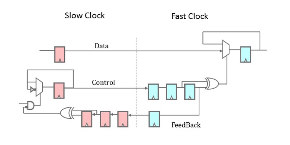 |
Perhaps some of you may have seen this before. It’s a two phase clock transfer circuit. While you may have seen it before, this was quite new to me. It took me a while after seeing this diagram to fully get a grasp on how this proposal was different–and then to make it better.
As with the original design, data is first clocked in the one domain, and then held constant until it’s transferred to the second domain. The output value of this design, at the new clock domain, never changes except on the positive edge of the new clock domain. (Clock crossing changes are hidden internally.) Similarly, as with the first design, there are two flip-flop synchronizers in both paths. Well, almost: the control path has a sort of modified three flip-flop synchronizer–but we’ll get to that in a moment.
 |
The big difference is that the data updates any time the control line, previously called a request line, changes. Before, we sent data by asserting a request line, and so new data was indicated by a positive edge. We then required the request line clear before sending a new piece of data–or we’d never be able to generate a new positive edge. This updated two-phase design sends a request by changing the control line–either positively or negatively. Once the change has been observed in the feedback path, this updated design doesn’t wait to clear the control line back to its original value, but rather uses the next change in the control line to send a new value. This removes the requirement for the second round trip to clear the control lines before going back around again. As such, this is a two-phase data crossing design.
So, how might we build this?
The design
For the sake of discussion, let’s use the basic AXI stream protocol. This will allow back pressure at both the input and the output. Better yet, if you don’t need this back pressure, then just tie the ready wires to one. We could also use this basic protocol to pass a strobe across clock domains: tie the readies to one, then any time the valid is asserted on the input (provided it’s not raised too often) will result on a single valid being asserted at the output.
 |
Fig. 5 shows our basic portlist above, enumerated again below.
module tfrvalue #(
		parameter	W = 32
	) (
		input	wire		i_a_clk,
		input	wire		i_a_reset_n,
		input	wire		i_a_valid,
		output	wire		o_a_ready,
		input	wire	[W-1:0]	i_a_data,
		//
		input	wire		i_b_clk,
		input	wire		i_b_reset_n,
		output	reg		o_b_valid,
		input	wire		i_b_ready,
		output	reg	[W-1:0]	o_b_data
	);

	// Register declarations
	localparam	NFF = 2;
	reg			a_req, a_ack;
	reg	[W-1:0]		a_data;
	reg	[NFF-2:0]	a_pipe;

	reg			b_req, b_last, b_stb;
	reg	[NFF-2:0]	b_pipe;
I’ve used the prefix i_a_* to describe signals from the source side of this
transaction, and o_a_ready to capture any
back pressure
feedback on this side.
Similarly, the i_b_* and o_b_* prefixes describe the transaction on the
receiving side. As you can see, we’ll be following AXI’s handshaking protocol
for this exercise.
The first key to this algorithm is that on any incoming request, we’ll toggle a request value.
	initial	a_req = 0;
	always @(posedge i_a_clk, negedge i_a_reset_n)
	if (!i_a_reset_n)
		a_req <= 1'b0;
	else if (i_a_valid && o_a_ready)
		a_req  <= !a_req;
We’re also going to grab a copy of the data before moving cross clock domains.
	always @(posedge i_a_clk)
	if (i_a_valid && o_a_ready)
		a_data <= i_a_data;
This data copy is important. It allows the launching side to continue on,
knowing that it’s request has been sent. This will speed up your throughput
over forcing the sender to leave i_a_valid high while waiting for the
return path to set o_a_ready.
Now that we’ve changed a_req and copied the data, it’s time to actually
cross clock domains.
This is a basic two
flip-flop
clock domain crossing,
with the exception that we’re using a third
flip-flop
to keep track of the last value. We call this one-clock-ago value b_last.
	initial	{ b_last, b_req, b_pipe } = 0;
	always @(posedge i_b_clk, negedge i_b_reset_n)
	if (!i_b_reset_n)
		{ b_last, b_req, b_pipe } <= 0;
	else begin
		{ b_last, b_req, b_pipe } <= { b_req, b_pipe, a_req };
		if (o_b_valid && !i_b_ready)
			b_last <= b_last;
	end
There’s one additional trick to the definition of b_last above. Did you
notice that I didn’t set b_last until I knew that the prior output wasn’t
stalled? As you may recall, a stall would be any time
o_b_valid && !i_b_ready. This extra stall check wasn’t in the original
design I was given, but it helps to guarantee proper AXI stream
protocol
handling. This is where stalls will happen, if at all, but not until a prior
word has already
crossed clock domains
and set o_b_valid to indicate that
there’s a word ready to be received. This also spares us some throughput,
since the receiving side can accept this data immediately if desired.
b_last is therefore true once the word has
crossed clock domains and
once it has been accepted on our output port. That means we can now start
sending the acknowledgment back to the beginning–the a_* clock domain–even
before the outgoing word has been accepted (o_b_valid && i_b_ready) by
the receiving stream.
	always @(posedge i_a_clk, negedge i_a_reset_n)
	if (!i_a_reset_n)
		{ a_ack, a_pipe } <= 2'b00;
	else
		{ a_ack, a_pipe } <= { a_pipe, b_last };
Once this flag returns to the original clock domain, we can then compare it to
a_req in order to know the round-trip is complete. Until a_ack matches
a_req, a transfer remains in progress and so o_a_ready needs to be false.
assign o_a_ready = (a_ack == a_req);Notice that, unlike the four-phase clock transfer, we can’t depend upon the
value of a_ack to get this result, but rather need to compare a_ack to
a_req. That’s one of the keys to the success of this two-phase algorithm.
Let’s now go back to the output port on the receiving side. We’ll move our
word across that final clock whenever b_last isn’t equal to b_req.
	always @(*)
		b_stb = (b_last != b_req);
We also need to do a protocol check. If ever !o_b_valid || i_b_ready, we
can set the output. However, we don’t want to set o_b_data based upon
a_data unless we are confident that a_data has held steady for at least
one clock period in the new domain. That way, we’re guaranteed there won’t
be any
cross clock domain
issues with it. Hence, we’ll only adjust
o_b_data if b_stb is high, telling us that there’s a cross-clock data
request pending.
	initial	o_b_data = 0;
	always @(posedge i_b_clk)
	if (b_stb && (!o_b_valid || i_b_ready))
		o_b_data <= a_data;
We’ve also discussed setting an AXI stream valid before. As with setting the data component, there’s a strict pattern to setting valid:
	initial	o_b_valid = 0;
	always @(posedge i_b_clk, negedge i_b_reset_n)
	if (!i_b_reset_n)
		o_b_valid <= 1'b0;
	else if (!o_b_valid || i_b_ready)
Once you follow the pattern, all that’s left is to set the o_b_valid value
to whatever your design requires. This time, we’ll set it to b_stb to
indicate there’s a new value arriving on the new clock.
o_b_valid <= b_stb;That’s the design. It’s pretty basic.
I suppose I should offer a word about asynchronous resets. This design uses them, even though I recommend against them in general. Why? Well, cross clock domain designs often require asynchronous resets. Without the asynchronous reset, there’s no real way to guarantee that both sides are reset in proper order.
Indeed, while writing this article, I had the opportunity of examining another similar design that didn’t use asynchronous resets. That design had no feedback to each clock domain to know when the reset in the other clock domain had completed. As a result, SymbiYosys found many ways of violating the reset assumptions within that design. For example, SymbiYosys found a way to launch a first value from the sending to the receiving domain, followed by a reset and then a second value, only to see the first value end up in the new domain after the reset.
Yes, those asynchronous resets are an important part of this design.
The next step, though, is the fun part: verifying that this design crosses clock domains properly.
Formal Verification
The first step to formally verifying any cross-clock
domain
transfer is to adjust the SBY
file to
set the multiclock on
option.
This is a minimum requirement of any design that uses more than one clock.
We’ll then need to get access to the formal timestep, gbl_clk by using the
Yosys (* gclk *) attribute.
(* gclk *) reg gbl_clk;In order to use $past() successfully, you’ll also need an f_past_valid*
type of value. In this case, there are three separate clocks–each of which
need an f_past_valid* check. I’ve labeled each of these with a suffix
identifying the clock they are associated with: the formal time step, the
incoming (launching or sending) clock on the _a_ interface, and then the
clock on the outgoing (destination, or receiving) _b_ interface.
			reg		f_past_valid_gbl, f_past_valid_a,
					f_past_valid_b;

	initial	f_past_valid_gbl = 0;
	always @(posedge gbl_clk)
		f_past_valid_gbl <= 1;

	initial	f_past_valid_a = 0;
	always @(posedge i_a_clk)
		f_past_valid_a <= 1;

	initial	f_past_valid_b = 0;
	always @(posedge i_b_clk)
		f_past_valid_b <= 1;
We have two more pieces of boiler plate left. First, we’ll need to create a clock, and then assume our two resets are properly related. Let’s start with the clocks.
We’ll “generate” a clock by adding an arbitrary step to a counter. We can then assume the incoming clocks are equal to the MSB’s of each counter.
	(* anyconst *)	reg	[3:0]	f_step_a,  f_step_b;
			reg	[4:0]	f_count_a, f_count_b;

	always @(posedge gbl_clk)
	begin
		f_count_a <= f_count_a + { 1'b0, f_step_a } + 1;
		f_count_b <= f_count_b + { 1'b0, f_step_b } + 1;
	end

	always @(*)
		assume(i_a_clk == f_count_a[4]);

	always @(*)
assume(i_b_clk == f_count_b[4]); |
This is your basic fractional clock divider circuit that we’ve covered many times before. Do be careful when you build one of these for a formal proof: the number of bits in the divider will drive the length of the proof. As it is, this proof as written will take 33 steps to verify against all possible faults using a 5-bit counter. You can see how this would change with other counter lengths in Fig. 6.
Normally I would assume that the step is greater than zero and less than or equal to half the range. Here, I’ve found another way of insisting on this property–by using a step of one less bit than the counter’s bit width and adding a constant one to it. This guarantees that each counter will step forward, and also that it won’t step forward so far that the counter appears to go backwards.
That should handle assuming the existence of two incoming clocks.
The next step is to handle the two resets. As we did for the asynchronous FIFO, we’ll want to assume that the design starts in reset and that both resets will fall together or never at all.
	always @(*)
	if (!f_past_valid_gbl)
		assume(!i_a_reset_n && !i_b_reset_n);

	// Both resets will always fall together
	always @(posedge gbl_clk)
		assume($fell(i_b_reset_n) == $fell(i_a_reset_n));
This is also going to force all of our properties onto the global clock.
From here on out, we won’t be able to use any always @(*) assert();
statements. If we did otherwise, any such combinatorial assertions would get
applied before this assumption was applied. For example, we might see one
reset becoming active prior to the other. If we instead trigger any assertions
on always @(posedge gbl_clk), the resets will behave properly.
Just to see what I’m talking about here, consider the trace shown in Fig. 7 below.
 |
In this picture, the formal proof failed when a_req suddenly dropped,
due to the sending side reset getting activated before the receiving side
reset. We can delay this check by one time cycle by using transitioning
our always block on gbl_clk instead of @(*)–something you’ll see more of
as we go along.
Let’s move on and force our input values to be clock synchronous, while verifying that our outputs are also clock synchronous.
One of the sad realities of multi-clock domain proofs is that you have to
assume the inputs are synchronous to their respective clocks–something that you
get for free when running proofs with a single clock only. Here, we’ll
assume that i_a_valid and i_a_data are synchronous to the i_a_clk.
We’ll also force i_a_reset_n to only rise synchronous to i_a_clk as well:
asynchronous reset assertion, synchronous release as it is sometimes called.
	always @(posedge gbl_clk)
	if (!$rose(i_a_clk))
	begin
		assume(!$rose(i_a_reset_n));
		assume($stable(i_a_valid));
		assume($stable(i_a_data));
		if (i_a_reset_n)
			assert($stable(o_a_ready));
	end
We’ll also add an assertion above that o_a_ready is stable unless the
clock changes. This follows my master rule of formal verification: assume
inputs, assert any local state or outputs. However, since we are using an
asynchronous resets,
this value might change if the reset is ever activated. Since we know the
reset will last more than one clock cycle, we can just escape the assertion
here if the reset is ever active.
We can just about repeat those same properties on the _b_ clock controlling
our outputs. The difference here is that they now need to be assertions instead
of assumptions, since we are applying them to outputs. The only two
exceptions are the reset in the B clock domain and the ready signal
i_b_ready, which are the only remaining inputs on this side.
	always @(posedge gbl_clk)
	if (!$rose(i_b_clk))
	begin
		assume(!$rose(i_b_reset_n));
		if (f_past_valid_b && i_b_reset_n && $stable(i_b_reset_n))
		begin
			assert($stable(o_b_valid));
			assert($stable(o_b_data));
		end
		if (i_b_reset_n)
			assume($stable(i_b_ready));
	end
You might notice that I’m requiring the o_b_data value to be synchronous
with the destination clock. While this isn’t strictly required, I find it to
be good form. Another common approach is to insist that it is synchronous
with the destination clock only if o_b_valid is true, and trust the
downstream logic to handle it properly.
Now that we are set up, it’s time to address the key components of any proof. We’ll start with the AXI stream protocol interface properties. Here, we assume these properties of our inputs:
- Valid gets cleared following any reset
- As long as an outgoing request is stalled, it isn’t allowed to change.
	always @(posedge i_a_clk)
	if (!f_past_valid_a || !i_a_reset_n)
		assume(!i_a_valid);
	else if ($past(i_a_valid && !o_a_ready))
	begin
		assume(i_a_valid);
		assume($stable(i_a_data));
	end
We then repeat those properties, only this time as assertions applied to our outputs.
	always @(posedge i_b_clk)
	if (!f_past_valid_b || !i_b_reset_n)
		assert(!o_b_valid);
	else if ($past(o_b_valid && !i_b_ready))
	begin
		assert(o_b_valid);
		assert($stable(o_b_data));
	end
Once our design passes these properties, we’ll know it is AXI stream compliant.
Taming the induction
engine
can be a bit of a challenge. In this case, we
need to make certain that the various ack, pipe, last, and req signals
are consistent. These registers essentially form a changed pulse, expressed
as a shift register, through time. Therefore, let’s place these values
together into a shift register and make sure the shift register only takes
on acceptable values.
	always @(posedge gbl_clk)
	case({ a_ack, a_pipe, b_last, b_req, b_pipe, a_req })
	6'b000_000: begin end
	6'b000_001: begin end
	6'b000_011: begin end
	6'b000_111: begin end
	6'b001_111: begin end
	6'b011_111: begin end
	6'b111_111: begin end
	6'b111_110: begin end
	6'b111_100: begin end
	6'b111_000: begin end
	6'b110_000: begin end
	6'b100_000: begin end
	6'b000_000: begin end
	default: assert(0);
	endcase
Incidentally, this was the assertion I changed to always @(*) in order
to demonstrate the problem in Fig. 7 above.
I personally like this case statement means of expressing this sort of
thought, and so I’ve used it often in many of my designs.
We have one final assertion–the one we’re doing this for, and that is that
the a_data register won’t be changed for at least one i_b_clk cycle
before it is read. This guarantees that we won’t be suffering from any
metastability
issues on the data register.
	always @(posedge i_b_clk)
	if ( (!(&{b_req, b_pipe})) && ({b_req, b_pipe} != 0) )
		assert($stable(a_data));
For the most part, this proof is boiler plate. It’s boiler plate clock domain crossing properties, boiler plate properties to describe something synchronous with a clock, and boilerplate AXI stream properties.
What isn’t here is a property to verify the correctness of the output data, nor any properties to prove that the number of outputs equals the number of inputs. For those, I’ve only desk checked the design so far. At this point, that’s been good enough, although I may need to come back and do a better job of that as time goes on.
Cover Checks
That leaves us with only one question, how well does this design work?
To answer that question, I thought I might count the number of times a
valid is available and ready on the b outgoing interface. Given that a
cover() check will return the first possible time an item becomes valid,
this should also be a good check of the speed of the interface as a whole.
Just for fun, I also added in the requirement that the outgoing data change with the count of the number of outgoing items.
	initial	cvr_stbcount <= 0;
	always @(posedge i_b_clk, negedge i_b_reset_n)
	if (!i_b_reset_n)
		cvr_stbcount <= 0;
	else if (o_b_valid && i_b_ready && (o_b_data[3:0] == cvr_stbcount))
		cvr_stbcount <= cvr_stbcount + 1;
That left me with the ability to check throughput. However, after my first
cover check, cover(cvr_stbcount[3]) failed, I had to back up and start over.
I replaced that cover check therefore with several intermediate steps.
	always @(*)
	begin
		cover(cvr_stbcount == 1);
		cover(cvr_stbcount == 2);
		cover(cvr_stbcount == 3);
		cover(cvr_stbcount == 4);
		cover(cvr_stbcount == 5);
	end
This allowed me to determine how many formal timesteps would be needed for each step. It also allowed me to answer the question of how much patience I had. In this case, five results required about nineteen seconds and six clock domain crossings weren’t really necessary. (Eight might’ve taken into the next century.)
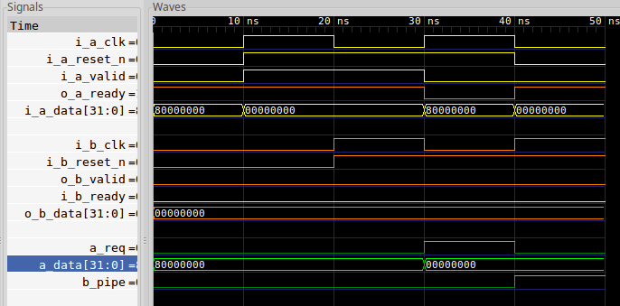
Here’s how the transfer looks.
 |
This is twice as fast as our previous method of moving data across clock clock domains. Just for reference, I’ve posted the older, slower, 4-phase implementation as well, and I’ve shown a before and after comparison below.
 |
Given that there’s little to no logic difference between the two phase and four phase CDC word transfers algorithms, I think I’m going to recommend the two phase approach from now on.
Conclusion
The two-phase handshake method of moving values from one clock domain to another isn’t about speed. It’s not. If you want speed and throughput, use an asynchronous FIFO. This method is instead about moving data coherently from one clock domain to another for a minimum amount of logic. It works independent of the speed of the two clocks: A can be faster, or B, it doesn’t matter, this method will work both ways. Indeed, we just proved that it would work for arbitrary clocks A and B.
The fascinating part of this upgrade over the four-phase handshake is that it is a no cost upgrade to our data transfer algorithm. Whereas our prior design used four Xilinx LUTs, this new and updated design also uses four LUTs while achieving twice the speed.
To this, I thank my reader for bringing this design approach to my attention.
For God hath not given us the spirit of fear, but of power, and of love, and of a sound mind. (2Tim 1:7)