
Building a custom yet functional AXI-lite slave
 |
Last year, we discussed how to verify an AXI-lite slave peripheral. To do this, we asked Vivado to generate an example AXI-lite peripheral and then added a reference to an AXI-lite property file and about 20 more lines of code to our design. Much to my surprise, Vivado’s AXI-lite peripheral didn’t pass formal verification. The core failed because it didn’t properly drop the ready lines to prevent an incoming transaction in the case where the outgoing acknowledgement channel was stalled.
We also noticed that Xilinx’s demonstration core as designed could only ever ever process a single transaction for every two clocks ticks, limiting its maximum throughput. No simple code adjustment would fix this.
That post referenced a core generated by Vivado
2016.3.
Since that time, I’ve also had a chance to
download and examine Vivado’s 2018.3 AXI-lite demonstration core. While
superficial changes have been made to this example core, it still suffers
from the same basic design flaws: unless the outgoing ready signals on the two
acknowledgment channels, both for S_AXI_RREADY and S_AXI_BREADY, are
dependably held high the
core
will drop acknowledgments. This is fundamentally bad, since it could cause a
CPU
to lock up hard. Worse, since it would be caused by the vendor’s
demonstration code, no one would think twice to examine it for an error.
For the sake of those who wish to work with an AXI-lite slave peripheral, let’s take a moment and examine how we might build a better AXI-slave.
Goals for any Bus Component
Whenever I build a bus component, whether it be a slave or a master, I start with three basic design criteria.
-
First, the bus component must maintain the rules of the road for the bus it is on. In the case of an AXI-lite bus, that means we need to examine the AXI-specification to determine how our code must behave.
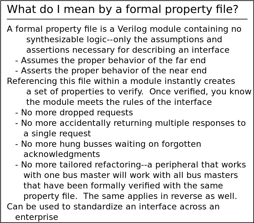
Once we’ve done that once, we can then capture this behavior in a formal property file that can then be used later to verify any other bus component. Such property files are great timesavers, since they typically only need to be built once, and yet they can then be used to verify any number of design components.
A common question I often get from corporate clients new to formal verification is, where do I start? My answer is often, “Start by building property files for the interfaces you support,” for this very reason: for a small amount of formal verification work, you can get a tremendous return on your investment.
Today, we’ll be reaping a return on our last AXI-lite investment.
My next two goals are performance related.
-
Maximum throughput
Once the component obeys the rules of the bus, my next priority is maximum throughput. A bus component must support the highest throughput possible. Think of it this way, the speed of the entire CPU portion of the design depends upon the speed of the bus. High performance is achieved by pipelining multiple transactions to the bus in a group. The higher the throughput is, the faster the CPU (or whatever bus master) can perform its functions.
Several individuals have posted both on Xilinx’s forum and Digilent’s forum about the MicroBlaze computer being horrendously slow [1] [2] [3] [4] [5]. The measurement is typically made by examining how fast the processor can toggle a general purpose output fed into an oscilloscope. While I’ll admit this isn’t a great measure of CPU performance, it is a somewhat decent measure of peripheral bus performance. (Incidentally, the ZipCPU can toggle a GPIO peripheral about 12x faster.)
There is no reason why a basic GPIO driver, as an example, needs two clocks for every transaction.
We’ll create a bus component in a moment that can handle one transaction on every clock.
-
Minimum latency
By latency I mean the number of clock cycles it takes from when the CPU makes a request until the response comes back from the peripheral. Most of the clock cycles used during the request will be consumed by the CPU first and then the interconnect, meaning that there isn’t all that much that a peripheral designer can do to affect the latency associated with accessing his component.
What he can do, however, is make certain that he doesn’t increase that latency by how he processes the request.
AXI requires that all bus signals must be registered on the clock edge. This means that the minimum latency through any specification compliant AXI-slave peripheral can never be better than a single clock cycle. The core presented below will achieve this minimum latency.
-
My last criteria, minimum area, is often lost after meeting the first three. In general, a design that meets the first three criteria is often so constrained that there’s not much more you can do to achieve minimum area. This is why the choice of a bus standard is so important to anyone designing for low area/minimum cost: design choices have consequences.
Overall system performance depends upon the first three design goals. High performance is fairly easy to meet using the Wishbone bus–which is one of the reasons why I like it so much. With AXI-lite, however, the bus requirements and maximum throughput goal can seem contradictory. It’s certainly not obvious, and so it’s worth illustrating how to make this happen.
Therefore let’s examine how to make an AXI-lite slave. I’ll focus on a RAM based design. Indeed, if we do this right, then our design should be able to map into block RAM. (My first draft didn’t meet this criteria.) Either way the design approach will be quite appropriate for a typical register-based slave peripheral.
Finally, before beginning to look at how we’d do this, let’s just note that of the two types of transactions, read and write, the AXI read channel is simplest to implement. Unlike the write channel, there’s only the one request channel called the read address channel going into a read transaction. The write channel, on the other hand, requires both an address and a data channel feeding it, as shown in Fig. 1 above. Therefore let’s examine the read channel first, and then apply the lessons we learn from the read channel to the write channel in the following section.
Read Channel Processing
Sometimes I like to sprint into code and just see how far I can get. In this
case, such a sprint into the read channel implementation appears easy:
every time we get an S_AXI_ARREADY && S_AXI_ARVALID we want to set
axi_rvalid on the next clock. As long as S_AXI_RREADY remains true, this
is sufficient for high speed interaction.
always @(*)
	axi_arready <= 1'b1;

always @(posedge i_clk)
if (!S_AXI_ARESETN)
	axi_rvalid <= 0;
else if ((S_AXI_ARVALID)&&(axi_rready))
	axi_rvalid <= 1'b1;
else if (S_AXI_RREADY)
	axi_rvalid <= 0;

always @(posedge i_clk)
	axi_rdata <= slv_mem[S_AXI_ARADDR[AW+ADDR_LSB-1:ADDR_LSB]];
Note that we’re following Vivado’s notation here, and using S_AXI_* to
describe any external signals, whereas we’ll use both the axi_* and
S_AXI_* prefixes to describe any internally generated
AXI
signals.
 |
Fig. 2 on the right illustrates how this scheme might work. Following any
clock period where both S_AXI_ARVALID && S_AXI_ARREADY are true,
S_AXI_RVALID is set with the appropriate result on the next clock. So far,
this is about as easy as
Wishbone
was.
The problem with the approach outlined above is easily discovered
when we attempt to
verify its functionality.
It’s also the same basic logic the Vivado generated
core
was been using: if S_AXI_RREADY were always true, this would pass as working
code. Nothing in the AXI-specification,
however, requires that S_AXI_RREADY be guaranteed to be true. Indeed, I
have to believe the authors of the
AXI specification
were quite proud of creating a
bus
interface that might respond to “back
pressure”
as a stall on an outgoing channel is called.
 |
Fig. 3 on the left shows what this naive implementation might lead to when
the S_AXI_RREADY line not held high.
In particular, we are required to hold the outgoing data constant any time
axi_rvalid && !S_AXI_RREADY. Did you notice how the blue transaction in this
figure got lost? This would be a catastrophic bug in our code. Notice also
how there’s an empty clock cycle in the return channel between the brown return
and the white return, precisely where the blue return should be?
Two realities lead to this bug. The first is that we need to stall, i.e. lower,
the axi_arready line when the response ready, S_AXI_RREADY, is low and
S_AXI_RVALID is high. (The
AXI-specification
is very clear that setting the axi_rvalid line cannot depend up
S_AXI_RREADY being set initially.) A straightforward implementation might
look like,
initial	axi_arready <= 1'b1;
always @(posedge S_AXI_ACLK)
if (!S_AXI_ARESETN)
	axi_arready <= 1'b1;
else if (S_AXI_RVALID && !S_AXI_RREADY)
	axi_arready <= 1'b0;
else
	axi_arready <= 1'b1;
This implementation, however, would cause the bug shown above in Fig. 3 above: the ready signal is only dropped after a transaction is lost! This is a catastrophic bug.
We could try to simplify this approach and just state that,
assign axi_arready = !axi_rvalid;While this would meet our bus requirements, it would violate our maximum throughput goal.
Another simple fix would be to set the axi_arready signal combinatorially,
so that
always @(*)
axi_arready = !S_AXI_RVALID || S_AXI_RREADY; |
This appears as though it might solve all of our problems. A trace built upon this logic is shown in Fig. 4 on the right.
Only it doesn’t solve our problems. It violates our first goal, since the
AXI specification
is quite clear: all signals, axi_arready included, must be registered. That
is, they must all be set on a clock edge. Adjusting axi_arready to meet
this standard will force a single clock delay in processing.
If we try to register axi_arready while maintaining a
throughput
of one transaction per clock, then we are forced to deal
with accepting a transaction before we realize we should’ve been stalled.
Such a transaction will need to be
buffered
within our core.
We studied how to do this back in 2017, under the name of a “buffered handshake.” Eric LaForest has recently posted a similar description, only he called it a “Skid Buffer”. However, I have yet to present code that will perform this handshake here on this blog. Until now.
Sadly, the design is not trivial. LaForest makes it look easy, although I tend to get confused every time I try this. Traces just don’t do it justice. Therefore, let’s examine how this might work through a series of figures.
 |
We’ll start with Fig. 5 on the right. This figure shows the beginning of the transaction, as the master creates a read request to send to the slave. We’ll assume that all of the ready signals are true initially, so this request is immediately accepted by the slave.
This is the way we want things to work.
Some might even argue that this is how slaves are normally accessed: one cycle at a time separated by idle cycles on both sides. This was something I discussed in my 2016 ORCONF presentation as well (see slides 26-27), since the Wishbone classic bus can never handle more than one transaction every three clocks as a result. We’ll reflect for a moment on the reality that the ZipCPU is more than capable of issuing multiple bus requests on adjacent clocks, and then we’ll ignore this piece of advice and continue with a second access following immediately after the first one.
 |
Fig. 6 illustrates the slave returning the initial request as a response to the master. This is on the next clock, so we are still meeting our maximum throughput requirement of a single clock. During this time, the master sends a second request to the slave.
Again, this is the way things are supposed to work. We’re just pushing data through at high speed, one transaction on every clock and meeting our throughput requirements.
 |
Fig. 7 shows the beginning of our problems. In Fig. 7, the master
lowers his S_AXI_RREADY signal (now shown in red), stalling the return
bus.
It will now take the slave another clock period, i.e. until Fig. 8, before
the slave can lower S_AXI_ARREADY since S_AXI_ARREADY is required
to be a clocked signal. This means that the slave must accept a second
request, the request marked number three in Fig. 7, while still waiting
for its second response to the master to be accepted.
There’s no other way to handle this new request than to buffer this next transaction within the slave. This means that that the slave will need to hold on to two separate transactions any time the read address channel is busy while the read response channel is stalled.
 |
On the next clock, shown in Fig. 8, the slave can finally lower the
S_AXI_ARREADY line to stall the input. As we noted above, the slave is
required to hold onto both request number three and the second response as
long as the input ready line, S_AXI_RREADY is stalling our whole system.
Failing to do this means that a transaction would get lost in this shuffle.
Now that both request and response channels have stalled, the system can remain in this state indefinitely.
 |
Eventually, the master will raise the ready line, as shown in Fig. 9 on the right. Once this happens, the second response can cross the channel.
Further, the third request can move from the internal buffer to the output position on the next clock.
Because it takes a clock edge to lower the stall signal, request number four will remain stalled this cycle.
 |
Now when we get to Fig. 10, the slave has finally raised its ready signal,
S_AXI_ARREADY, meaning request number four can proceed to the response
channel finishing our example.
This is the concept we are going to try to implement below.
Usually when I start to implement something like this, I create a buffer
is-valid signal to indicate that there’s valid information in the buffer.
However, if you look back over the last several charts, you can see that any
time S_AXI_ARREADY is low, there’s data in the
buffer.
Hence, we’ll use !S_AXI_ARREADY as our signal that we have something in
this extra
buffer
position.
 |
Fig. 11 illustrates the other situation that often confuses me, since I will catch myself trying to stall the upstream channel anytime the downstream channel is stalled.
That’s not how this buffered handshake works, however. To do this right, the upstream channel should only stall if the downstream channel is stalled and if there’s an item in the buffer. Both criteria need to be true.
We’ll need this tidbit as we move forward.
Let’s also try to simplify things with two helper variables. The first,
valid_read_request, will be true if ever there’s been a request on the
read channel, either currently or one that has since stalled.
assign valid_read_request = S_AXI_ARVALID || !S_AXI_ARREADY;Similarly, we’ll assign read_response_stall to indicate that there’s a
valid response currently in the return channel but that the ready flag
is low so that it cannot move forward.
assign read_response_stall = S_AXI_RVALID && !S_AXI_RREADY;So let’s work through our downstream implementation first.
If the downstream read channel is stalled, that means axi_rvalid is true
and must remain so until the stall is clear.
	initial	axi_rvalid = 1'b0;
	always @( posedge S_AXI_ACLK )
	if (!S_AXI_ARESETN)
		axi_rvalid <= 0;
	else if (read_response_stall)
		// Need to stay valid as long as the return path is stalled
		axi_rvalid <= 1'b1;
Likewise if the response was valid before and the downstream response channel was stalled, then we need to maintain the response on the output channel until it has been accepted.
	else if (valid_read_request)
		axi_rvalid <= 1'b1;
In all other cases, we’ll release the response channel and lower our valid signal, since all transactions have by now been accepted.
	else
		// Any stall has cleared, so we can always
		// clear the valid signal in this case
		axi_rvalid <= 1'b0;
But what about the data content of this channel?
First, I’m going to keep this simple. Our slave will never return any type of bus errors. You can read about what I dislike about allowing slaves to create bus errors in my Wishbone properties post if you are interested. Not returning any bus errors means the response type is constant.
	always @(*)
		axi_rresp  = 0;	// "OKAY" response
That was too easy.
The response data payload is just a touch harder, although we can split into three basic steps.
First, on any valid read address transaction, we’ll set the address for our buffer. If our buffer doesn’t contain a valid read request, then this will just be a don’t care address. Even better, as long as the buffer isn’t already full, then we can set the buffer address independent of whether there’s a request we are accepting or not. This helps to satisfy our minimum logic goal.
	always @(posedge S_AXI_ACLK)
	if (S_AXI_ARREADY)
		pre_raddr <= S_AXI_ARADDR;
The second step is to determine which address to read from. If our
buffer
has valid data in it, then we’ll want to read from this
buffered
address, dly_addr. In all other cases we can read directly from the
address provided on the
bus.
	always @(*)
	if (!axi_arready)
		rd_addr = pre_raddr;
	else
		rd_addr = S_AXI_ARADDR;
The third step is to do the actual read. In the case of a RAM, extraneous reads never hurt. Therefore we can read any time the outgoing channel isn’t stalled–regardless of whether we have an active read request or not.
	always @(posedge S_AXI_ACLK)
	if (!read_response_stall)
		// If the outgoing channel is not stalled (above)
		// then read
		axi_rdata <= slv_mem[rd_addr[AW+ADDR_LSB-1:ADDR_LSB]];
If you were implementing any hardware registers instead of a block RAM, this is where you would implement the read from those registers. You might also to adjust this logic as well: sometimes read transactions have side effects, such as in my Cyclone-V design. In that case, you’d want to add a bit more logic, perhaps even the following:
	always @(posedge S_AXI_ACLK)
	if (!read_response_stall
		&&(!OPT_READ_SIDEEFFECTS || valid_read_request))
		// If the outgoing channel is not stalled (above)
		// then read
		axi_rdata <= slv_mem[rd_addr[AW+ADDR_LSB-1:ADDR_LSB]];
That sets our response data. Now for the upstream S_AXI_ARREADY which, as
I mentioned above, also determines when or if we have an item in our buffer.
The logic here starts by looking downstream. If we have something in our
buffer or about to be in our buffer, that is if we have a
valid_read_request, then we’ll need to stall the upstream
channel as well.
	initial	axi_arready = 1'b0;
	always @(posedge S_AXI_ACLK)
	if (!S_AXI_ARESETN)
		axi_arready <= 1'b1;
	else if (read_response_stall)
	begin
		// Outgoing channel is stalled
		//    As long as something is already in the buffer,
		//    axi_arready needs to stay low
		axi_arready <= !valid_read_request;
Here’s the difficult part: If the downstream channel is stalled, and the upstream channel is passing us data, then we need to accept the request into our buffer and then immediately stall the upstream channel.
		else
			axi_arready <= (!S_AXI_ARVALID);
Notice that we didn’t stall the upstream channel until there was a valid item in our buffer. This is the detail I always get confused by which I illustrated in Fig. 11 above.
Finally, if the outgoing response channel isn’t stalled, then we can set the read address ready line to be ready for the next transaction.
	end else
		axi_arready <= 1'b1;
That’s all there is to it, although I personally find the pictures above easier to understand than the code above. Indeed, if it weren’t for the formal verification tools, I might’ve gotten this code quite wrong.
One last figure in this section will illustrate how this logic works.
 |
Fig. 12 shows the results from a rather complex cover statement found at the end of the file. Here you can see that, yes, we did meet our requirements for both throughput and latency. The next piece of good news is that this logic passes our formal verification test–but I’ll have more to say on that further down. Finally, let me say that I found Figs. 5-11 more instructive about what was going on that the trace shown in Fig. 12 on the right.
For now, let’s turn our attention to the more difficult transaction: the write transaction.
Write processing
We now need to apply the lessons we just learned from the read channel to the write channel. The first lesson is that we’ll need a buffered handshake, and the second lesson is that the return ready signals will also indicate negatively whether or not buffer is full.
That’s the easy part.
If only the write channel were as easy as the read channel. Indeed, it would be if we were able to guarantee that the write address and write data would both arrive at our slave at the same time. Sadly, this is not the case. The two channels, write address and write data, may be separated by up to two clocks. We’ll need to synchronize those two channels here, however, since we can’t perform the write transaction internal to our slave without having both the required address and the required data. That then will be the challenge of this section.
Let’s think this through for a moment before sprinting ahead this time. We can complete a write transaction any time the following three conditions hold.
-
The outgoing response channel must not be stalled.
-
We must have the address of where we need to write. This can be either in our buffer, or coming directly from
S_AXI_AWADDR. Yes, we’ll need to buffer the address. -
We must have the data of what we wish to write as well. This also includes the write strobes, indicating which bytes in our data word need to be written. This channel will also need to be buffered, just like the write address channel.
As before, we can use !S_AXI_AWREADY to indicate that we have a value in
our address buffer, and !S_AXI_WREADY to indicate that we have a value in our
data buffer.
That’s going to be our basic approach. Now let’s just work through the various signals.
Our first step will be to define some helper variables, to make the logic below simpler. The first will indicate that we have a valid write address, either one coming in now or one in our buffer. The second is the same, but for write data. Finally, the third helper indicates that the outgoing channel is stalled.
	assign	valid_write_address = S_AXI_AWVALID || !axi_awready;
	assign	valid_write_data    = S_AXI_WVALID  || !axi_wready;
	assign	write_response_stall= S_AXI_BVALID  && !S_AXI_BREADY;
These three helper values will make it easier to express our logic below.
Let’s start with the write address channel ready signal, and the logic that would be appropriate if there were no write data channel. That is, set the ready on reset, then deal with the case where the outgoing buffer is stalled.
	initial	axi_awready = 1'b1;
	always @(posedge S_AXI_ACLK)
	if (!S_AXI_ARESETN)
		axi_awready <= 1'b1;
	else if (write_response_stall)
	begin
Now when I say that the outgoing buffer is stalled, I mean that S_AXI_BVALID
is true and so there’s a value waiting to be returned. I also mean that
S_AXI_BREADY is false, meaning that this value can’t go any where. This
leaves us with two conditions to check, as shown in Fig. 13 below.
 |
If the output channel is stalled and our buffer is either already full
or a new write address is available, then we need to make certain that
the write address channel is stalled. This is the case shown on the right above. Likewise if
the output channel is stalled and we just accepted a value, then we need to
lower the ready line of S_AXI_AWREADY. This is shown on the left above.
In either case, we need to drop the ready signal for this channel. However,
if there’s nothing in our buffer and S_AXI_AWVALID is low (not shown),
then we can just leave our buffer empty.
		// The output channel is stalled
		//	If our buffer is full, we need to remain stalled
		//	Likewise if it is empty, and there's a request,
		//	  we'll need to stall.
		axi_awready <= !valid_write_address;
That wasn’t too bad, and it was roughly identical to what we did before.
Now let’s look at the case where the output isn’t stalled, as shown in Fig. 14 below.
 |
The left side of Fig. 14 shows the case where a write data is coming into our core, and the right side shows the case where the write data is already within our core and stalled. In both cases, we’ll want to make certain that the write address channel is ready to accept an associated address.
But what’s happening on the write address channel? It doesn’t matter. Either an address is coming in or it isn’t. If no address comes in, then the write data channel will have to stall–not the write address channel. We are working through the write address channel, so that doesn’t impact us here.
	end else if (valid_write_data)
		// The output channel is clear, and write data
		// are available
		axi_awready <= 1'b1;
There’s one final condition, shown below in Fig. 15.
 |
What happens when there’s no data available from the data channel and a valid
address shows up? There’d be no data to go with it! We’ll have to then stall
until there’s data ready. Two examples of this are shown above in Fig. 15.
If neither example is fits, then we can set axi_awready otherwise we’ll
need to stall.
	else
		// If we were ready before, then remain ready unless an
		// address unaccompanied by data shows up
		axi_awready <= ((axi_awready)&&(!S_AXI_AWVALID));
Did you get all that?
The write data ready signal, axi_wready, has the same identical logic as
that of the axi_awready signal save that the write data and address channel
information are reversed.
	initial	axi_wready = 1'b1;
	always @(posedge S_AXI_ACLK)
	if (!S_AXI_ARESETN)
		axi_wready <= 1'b1;
	else if (write_response_stall)
		// The output channel is stalled
		//	We can remain ready until valid
		//	write data shows up
		axi_wready <= !valid_write_data;
	else if (valid_write_address)
		// The output channel is clear, and a write address
		// is available
		axi_wready <= 1'b1;
	else
		// if we were ready before, and there's no new data avaialble
		// to cause us to stall, remain ready
		axi_wready <= (axi_wready)&&(!S_AXI_WVALID);
What does it mean to buffer the transaction in this context? For the write
address channel, it means capturing the incoming address. Remember,
our buffer is valid any time axi_awready is low.
The bus requires that we capture this address any time
S_AXI_AWVALID && S_AXI_AWREADY. The reality, though, is that if
S_AXI_AWREADY is true, then we can capture the address regardless of
whether or not AWVALID is also true–since our address copy is a don’t
care if no request is active.
	// Buffer the address
	always @(posedge S_AXI_ACLK)
	if (S_AXI_AWREADY)
		pre_waddr <= S_AXI_AWADDR;
The same applies to the write data channel. We’ll want to make a copy of it any time we accept a value. Then, if we end up accepting a value while the output is stalled or likewise if we have no address, this will become the buffered value waiting to be written to the address that hasn’t yet been given.
As before, we’ll ignore the valid signal since these registers have don’t care
values if S_AXI_WREADY & !S_AXI_WVALID and it just simplifies our logic count.
	// Buffer the data
	always @(posedge S_AXI_ACLK)
	if (S_AXI_WREADY)
	begin
		pre_wdata <= S_AXI_WDATA;
		pre_wstrb <= S_AXI_WSTRB;
	end
In a moment we’ll do our write and move the operation to the output buffer. But not until the address and data are synchronized. Here, we pick between either the buffered address or the incoming address for that write.
	always @(*)
	if (!axi_awready)
		// Read the write address from our "buffer"
		waddr = pre_waddr;
	else
		waddr = S_AXI_AWADDR;
Likewise, we need to pick between the buffered data and the incoming data.
	always @(*)
	if (!axi_wready)
	begin
		// Read the write data from our "buffer"
		wstrb = pre_wstrb;
		wdata = pre_wdata;
	end else begin
		wstrb = S_AXI_WSTRB;
		wdata = S_AXI_WDATA;
	end
It is finally time to write to our slaves registers. Remember our three conditions for writing that we presented above? Here they are again: We can write if there’s a place available in the outgoing channel, if we have a valid address, and if we have valid data.
	always @( posedge S_AXI_ACLK )
	// If the output channel isn't stalled, and
	if (!write_response_stall
		// If we have a valid address, and
		&& valid_write_address
		// If we have valid data
		&& valid_write_data)
	begin
It’s been a while since I’ve discussed byte enable or select
lines. The basic
idea is that the S_AXI_WSTRB signal contains which of the various octets
on the bus should be written by the given value.
		if (wstrb[0])
			slv_mem[waddr[AW+ADDR_LSB-1:ADDR_LSB]][7:0]
				<= wdata[7:0];
		if (wstrb[1])
			slv_mem[waddr[AW+ADDR_LSB-1:ADDR_LSB]][15:8]
				<= wdata[15:8];
		if (wstrb[2])
			slv_mem[waddr[AW+ADDR_LSB-1:ADDR_LSB]][23:16]
				<= wdata[23:16];
		if (wstrb[3])
			slv_mem[waddr[AW+ADDR_LSB-1:ADDR_LSB]][31:24]
				<= wdata[31:24];
	end
Vivado’s auto-generated slave core
uses a for loop to walk through the various select lines and their associated
bytes. While this works, I find it harder to read than the code above.
Further, since Xilinx requires
that the AXI-lite bus
be only ever 32-bits wide, the code above should still be widely applicable.
That leaves only one step left: adjusting axi_bvalid to acknowledge
that a write has taken place. The code below almost follows our three
conditions above, though it skips the first one. As it turns out, it doesn’t
matter if the output is valid but the bus master isn’t ready:
we’ll set S_AXI_BVALID high either way using the logic below.
	initial	axi_bvalid = 1'b0;
	always @( posedge S_AXI_ACLK )
	if (!S_AXI_ARESETN)
		axi_bvalid <= 1'b0;
	//
	// The outgoing response channel should indicate a valid write if ...
		// 1. We have a valid address, and
	else if (valid_write_address
			// 2. We had valid data
			&& valid_write_data)
		// It doesn't matter here if we are stalled or not
		// We can keep setting ready as often as we want
		axi_bvalid <= 1'b1;
	else if (S_AXI_BREADY)
		// Otherwise, if BREADY was true, then it was just accepted
		// and can return to idle now
		axi_bvalid <= 1'b0;
Oops, I forgot one: as with the read channel, our write response won’t return any bus errors.
	always @(*)
		axi_bresp = 2'b0;	// "OKAY" response
That’s what it takes to write to an AXI slave peripheral tuned for high throughput. I hope the pictures along the way helped. I know I tend to struggle getting the logic right for a basic buffered handshake as we’ve done above. Without the verification component, I’m not sure I’d have much confidence doing this.
Fig. 16 below shows an example trace drawn from the logic of this core.
 |
The left side of this trace shows several examples of how the logic might stall. The right side, on the other hand, shows that this core truly can handle one transaction per clock.
Shall we discuss what it takes to verify this design? It’s actually really easy to do now that we have a formal property list put together for the AXI-lite bus.
Verification
Verifying this design isn’t all that much more difficult than the last design we verified. Really, it isn’t.
The first step is to instantiate our set of AXI-lite bus properties. This big ugly block of code only looks that way because there are so many signals associated with this protocol.
`ifdef	FORMAL
	// Allow a maximum of 2^4-1 or 15 transactions to be in flight at
	// any given time
	localparam	F_LGDEPTH = 4;

	wire	[(F_LGDEPTH-1):0]	f_axi_awr_outstanding,
					f_axi_wr_outstanding,
					f_axi_rd_outstanding;

	faxil_slave #(.C_AXI_ADDR_WIDTH(C_S_AXI_ADDR_WIDTH),
			.F_LGDEPTH(F_LGDEPTH))
		properties (
		.i_clk(S_AXI_ACLK),
		.i_axi_reset_n(S_AXI_ARESETN),
		//
		.i_axi_awaddr(S_AXI_AWADDR),
		.i_axi_awcache(4'h0),
		.i_axi_awprot(S_AXI_AWPROT),
		.i_axi_awvalid(S_AXI_AWVALID),
		.i_axi_awready(S_AXI_AWREADY),
		//
		.i_axi_wdata(S_AXI_WDATA),
		.i_axi_wstrb(S_AXI_WSTRB),
		.i_axi_wvalid(S_AXI_WVALID),
		.i_axi_wready(S_AXI_WREADY),
		//
		.i_axi_bresp(S_AXI_BRESP),
		.i_axi_bvalid(S_AXI_BVALID),
		.i_axi_bready(S_AXI_BREADY),
		//
		.i_axi_araddr(S_AXI_ARADDR),
		.i_axi_arprot(S_AXI_ARPROT),
		.i_axi_arcache(4'h0),
		.i_axi_arvalid(S_AXI_ARVALID),
		.i_axi_arready(S_AXI_ARREADY),
		//
		.i_axi_rdata(S_AXI_RDATA),
		.i_axi_rresp(S_AXI_RRESP),
		.i_axi_rvalid(S_AXI_RVALID),
		.i_axi_rready(S_AXI_RREADY),
		//
		.f_axi_rd_outstanding(f_axi_rd_outstanding),
		.f_axi_wr_outstanding(f_axi_wr_outstanding),
		.f_axi_awr_outstanding(f_axi_awr_outstanding));
If I wasn’t interested in passing induction, I might be willing to stop right here. However, induction is a powerful tool and I’ve learned to depend on its ability to prove that a design will maintain a set of properties for all time.
So let’s look at the few properties that are necessary for passing the induction step.
Let’s start by examining three read properties. First, if S_AXI_RVALID is
low, then there shouldn’t be any outstanding read transactions at all. Our
code should match the counter from within our
property set.
	always @(*)
	if (S_AXI_ARESETN)
	begin
		if (!S_AXI_RVALID)
			assert(f_axi_rd_outstanding == 0);
Second, if the output is valid but stalled, then we may have accepted either
one or two read requests. If we have something in our buffer, then
axi_arready will be low and we will have accepted two requests. In all other
examples, we’ll have only accepted one.
		else
			assert(f_axi_rd_outstanding == 1 + (axi_arready ? 0:1));
	end
Those same properties can now be applied to our write channel, but with one subtle difference. The write channel contains two separate channels whose counts must be checked.
First, if the output is valid then each channel, address and data, must have accepted at least one request. The two channels may have accepted a second request as well, but only if they currently have one buffered.
	always @(*)
	if (S_AXI_ARESETN)
	begin
		if (axi_bvalid)
		begin
			assert(f_axi_awr_outstanding == 1+(axi_awready ? 0:1));
			assert(f_axi_wr_outstanding  == 1+(axi_wready  ? 0:1));
On the other hand, if no output is valid, then each channel must either have nothing outstanding, or it must have one valid and be waiting on the other channel. These two options are shown in Fig. 17 below.
 |
They are described in properties below. Note that it is an error for both
buffers to contain a value if axi_bvalid is false.
		end else begin
			assert(f_axi_awr_outstanding == (axi_awready ? 0:1));
			assert(f_axi_wr_outstanding  == (axi_wready  ? 0:1));
			assert(!axi_awready || !axi_wready);
		end
	end
You can find a SymbiYosys script for this core here. Only twenty six steps are necessary to prove that we meet all of the bus properties I presented in our last AXI-lite article.
Cover properties
Only one requirement remains to be shown from our initial goals above. We’ve shown that we can meet our bus interface requirements, but can we truly accomplish maximum throughput as we wanted?
Let’s see if we can push four values through this slave, retiring one read
on each of four clocks. If S_AXI_RVALID && S_AXI_RREADY will be true any time
a return value is accepted, than if this value is high for four clocks in
a row we’ll know
our core
has the ability to as fast as the
specification
will allow it to go.
	always @( posedge S_AXI_ACLK )
	if ((f_past_valid)&&(S_AXI_ARESETN))
		cover(($past((S_AXI_RVALID && S_AXI_RREADY)))
			&&($past((S_AXI_RVALID && S_AXI_RREADY),2))
			&&($past((S_AXI_RVALID && S_AXI_RREADY),3))
			&&(S_AXI_RVALID && S_AXI_RREADY));
Why four clocks though? Because I wanted some confidence that this core could truly handle retiring one request per clock without requiring it be stalled while the pipeline filled up.
The same approach applies to the return path.
	always @( posedge S_AXI_ACLK )
	if ((f_past_valid)&&(S_AXI_ARESETN))
		cover(($past((S_AXI_BVALID && S_AXI_BREADY)))
			&&($past((S_AXI_BVALID && S_AXI_BREADY),2))
			&&($past((S_AXI_BVALID && S_AXI_BREADY),3))
			&&(S_AXI_BVALID && S_AXI_BREADY));
That concludes our examination of this core.
`endif
endmodule
We’ve now not only built an interface with a buffered handshake, but we’ve also managed to verify that it works. Indeed, I would have no confidence that this worked were it not for the formal verification.
Let me share another secret with you: Often, while writing articles like this
one, I’ll find something I want to tweak in the
example code I’m presenting.
Usually
this is to make the code easier to read and explain, although sometimes I
touch things up to remove extraneous logic as well. However,
I also want to make certain that the slightly changed code still works. As a
result, every time I make a change I’m re-running the formal verification
proof to
make certain I haven’t introduced changes in the process. Usually this means
I can greatly simplify a design for presentation. In this case, the
formal
tools also caught a check for if (ready && ready) instead of
if (valid && ready).
I might argue that formally verifying AXI-lite designs is really easy when using SymbiYosys! If you haven’t tried it yourself, let me encourage you to do so. Just the ability to verify an AXI-lite core alone and find bugs that Xilinx’s VIP wasn’t able to find should give you some confidence when using the tool. Wait, did I just say their VIP couldn’t find these bugs? While I really don’t know that to be the case, I am drawn to such a conclusion. I mean, why would they publish a broken code generator unless they had tried to verify it only to receive a false positive suggesting that it worked when it didn’t?
Conclusion
This is now the second article in a short series about the AXI-lite bus. The first article discusses how I created the AXI-lite property file which was used to verify the slave implementation we discussed above.
The repository containing this core also contains several bridge cores to include an AXI-lite to wishbone core, a wishbone to AXI-lite bridge and even a Wishbone to full AXI bridge. If you look around, you might also notice that I have a similar property files posted there for both the Wishbone and Avalon buses.
I’d like to come back to this topic in the future and discuss a full AXI to WB bridge as well as the properties necessary to verify it. That project and post, however, will need to wait for another day.
Another potential future post would be to discuss how easy it can be to build
the complex cover statements used to demonstrate
this core
above. Such an approach would offer an alternative to the sequences that
SVA supports but which the
free version of Yosys
does not. That will also need to wait for another day as well.
Judgment also will I lay to the line, and righteousness to the plummet: and the hail shall sweep away the refuge of lies, and the waters shall overflow the hiding place. (Is 28:17)