
Introducing the ArrowZip ZipCPU design, featuring the Max-1000
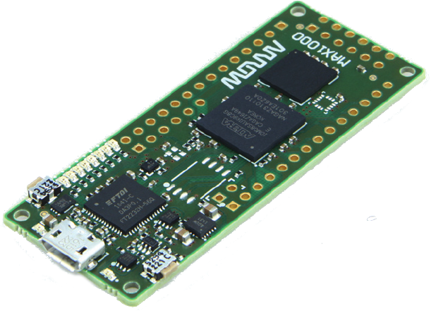 |
Some time ago, I wrote about the Max-1000 board sold by Trenz and distributed in the US by Arrow. In that post, I discussed some of the problems associated with getting a design running on the board, but also discussed its utility.
Indeed, for $30, the Max-1000 board is a nice entry board for beginners — once you get past the difficulty associated with building and loading a design onto the board, and once you get past the difficulty of getting an SDRAM controller to work on the board.
For all of these reasons and more, I thought it might be a fun board to build a demonstration design with. Better yet, as of last week, the design appears to be working! Yes, working: flash controller, SDRAM controller, and indeed everything but the accelerometer. (That’s still on my TODO list.)
Shall we take a walk through the various parts of the repository?
Let’s Play!
Let’s start out with a quick list of things you can do (currently) with the ZipCPU as found in the ArrowZip repository of mine.
First, there’s the CPU test. We’ve met this program before. It’s somewhat of a relic of time past when I used it to verify that the ZipCPU worked at all. Now, most of the CPU testing is done via formal methods, but this test remains. It’s usually the first program I will place onto a new ZipCPU design. As such, it runs from block RAM only. To run this from simulation, build the design (i.e. run make in the root directory) and then go into the sim/verilated directory, and run:
% main_tb ../../sw/board/cputestIt will take a moment to run, and a bit longer to handle the multiplication test, but pretty soon you’ll see the “All tests passed. Halting CPU.” line.
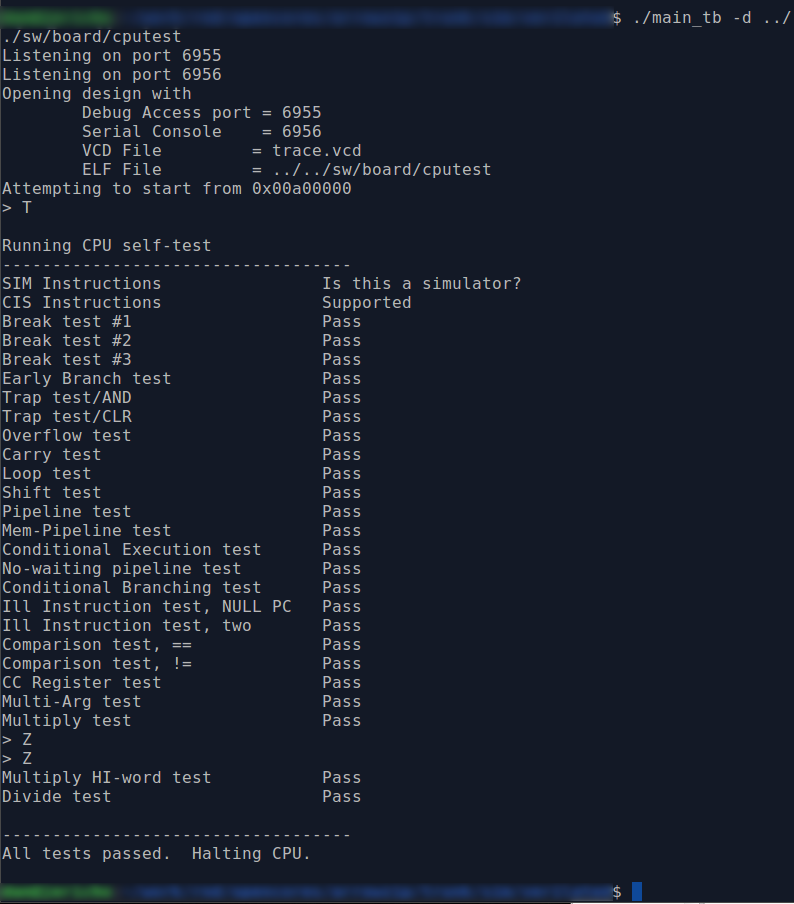 |
If you want to capture a trace of the entire run, just add “-d” to the
main_tb command line and run,
% main_tb -d ../../sw/board/cputestThis will create a trace.vcd file in your current directory that you can
view using GTKWave. Be prepared for it
to take a while, and to use more than 25GB of your hard drive.
On the other hand, if you want to load and test the design on
the FPGA board
itself, you’ll need to first build and load the design as discussed
earlier,
and then run
netuart
to bridge the serial port to a pair of network
ports. If we
assume the serial port connected to this device is at /dev/ttyUSB0, then you
would run
netuart
from the sw/host
directory as:
% netuart /dev/ttyUSB0While this
program
is running, you will be able to access the design through
the debugging bus
on TCP port 6955 and the serial port on TCP
port 6956.
Hence, to interact with the design, you’ll want to telnet to port 6956.
% telnet localhost 6956We can now load the CPU test into the ZipCPU and start it,
% ./zipload -r ../board/cputestYou’ll notice that the CPU test finishes almost instantaneously now–once it finishes getting loaded onto the board.
This is interesting, but what else can we do?
We can test our SDRAM memory using a memory test program created just for that purpose.
% ./zipload -r ../board/memtestThis program is a bit more confusing than the CPU test, since it doesn’t use the serial port interface. It works by writing to memory and then reading back from memory as part of one of four tests. After each test, the LEDs are adjusted, and after the last test the fourth LED is toggled and the test is restarted. If at any time the value read from the SDRAM doesn’t match the pseudorandom data that was written to it, all LEDs will be set and the CPU will halt. I would then bring up the ZipCPU in the (very basic) debugger to see what happened, although by now it should “just work” in case you wish to try it.
The third piece of ZipCPU software is “Hello World.”
This program runs from flash. As before, the zipload program can be used to load this program into the flash.
% ./zipload -r ../board/helloIt will take some time to program this design into the flash. To understand this extended time, remember that flash driver works by:
- First searching for any sectors (64kB each) that need to be erased (i.e. bits that need to be flipped from zero to one), and then
- Erasing those sectors, and so turning all the bits to ones.
- Once the erase is complete, the flash driver will re-read from the flash device to make certain that the erase has been successful.
- If the erase was successful, the driver will proceed page by page, i.e. 256 bytes at a time) through the flash. If any bit needs to be “programmed”, that is if it needs to be flipped from a one to a zero, then the whole 256-byte page will be programmed and then
- Read back again to verify the flash. design load.
This is a bit of a challenge on the low-logic serial port interface I call the Hexbus. Each byte needs to be read either once or twice to check the erase, and then read twice and written once for the program section. While the reads are done 32-bits at a time, transmitted using more than 80 bit intervals, the writes are done 8-bits at a time and transmitted using more than 80 bit intervals per byte. This is horribly inefficient, and I’m already considering ways to optimize this in the future.
Once the ZipCPU program, “Hello World,” is written to the flash, the design will start running, and will write out,
Hello, World!to the serial port and thus to the TCP/IP port 6956.
These are the three current ZipCPU examples I’ve written to date for this design.
There’s a lot more that can be done with this design that I haven’t (yet) done with it. For example, the MAX-1000 board has a 3-axis nano accelerometer on board. I’ve thought about using this accelerometer to create a level sensor. I’ve also thought about using this design as an unlicensed FM transmitter. Last time I did that, I used a XuLA-LX25 board to do it, and struggled with maintaining a non-standard configuration of my project.
Perhaps I should just teach the design to play 4x4x4 Tic-Tac-Toe as we did with the ZBasic (simulation only) design before it?
The possibilities are endless!
Command line access
The design and the components within it can also be accessed externally via C++ calls. It’s been a while since I discussed the DEVBUS interface that I use, but since that time the interface has hardly changed. My design still supports reading from and writing to the memory and peripheral address space within the design from external C++ host programs.
For example, there’s a dumpflash program in the sw/host directory. This program reads and dumps the state of the flash to a file on your host system. It is centered around a single line calling the DEVBUS interface:
#define	DUMPMEM		FLASHBASE
#define	DUMPWORDS	(FLASHLEN>>2)
//
// ...
//
        if (vector_read) {
		// One single call to the DEVBUS interface to read from the
		// flash in the design
                m_fpga->readi(DUMPMEM, BUFLN>>2, (DEVBUS::BUSW *)&buf[0]);
                byteswapbuf(BUFLN>>2, (DEVBUS::BUSW *)&buf[0]);
Alternatively, we could split our massively long 8MB data read into multiple reads, and read (and dump) one portion of the flash at a time.
        } else {
		// Alternatively
                for(int i=0; i<BUFLN; i+=4) {
                        DEVBUS::BUSW    word;

                        word = m_fpga->readio(DUMPMEM+i);

                        buf[i  ] = (word>>24) & 0x0ff;
                        buf[i+1] = (word>>16) & 0x0ff;
                        buf[i+2] = (word>> 8) & 0x0ff;
                        buf[i+3] = (word    ) & 0x0ff;

                        if ((i&0x01ffc)==0x01ffc)
                                fwrite(&buf[i&~0x1ffc], sizeof(buf[0]), 8192, fp);
                }
        } fclose(fp);
The design also supports a command line interface using the wbregs command we spoke of before. Basically, “wbregs address” will read from the given address and return the result to the command line. “wbregs address data” will similarly write the value “data” to the given “address”. What might you do with this?
The first thing I did with this was to try to debug my brand new flash controller. This controller is part of my new “Universal flash controller” project, and now marks the second flash chip that works with this new controller design. You can see the string of test commands I sent to the flash in the flashid.sh script. Only once I got the flash controller to the point where I could successfully read the manufacturer’s ID from the flash, did I then move towards replacing this script with a C++ program to do the same thing–only faster.
We could also have some fun and play with our stopwatch
peripheral.
Writing a 1 to the LSB starts the
stopwatch,
writing 0 to the LSB stops it, and
writing bit 1 (i.e. a two) will clear the
stopwatch.
$ ./wbregs stopwatch 1    # Start the stopwatch peripheral
00800048 (STOPWATCH)-> 00000001
$ sleep 2 # Wait two seconds
$ ./wbregs stopwatch    # Read from the stopwatch
00800048 (STOPWATCH) : [....] 80000202
$ sleep 6 # Wait six more seconds
$ ./wbregs stopwatch    # Read from the stopwatch again
00800048 (STOPWATCH) : [....] 80000806
$ sleep 2 # Wait another two seconds
$ ./wbregs stopwatch 0  # Stop the stopwatch
$ ./wbregs stopwatch    # Read, now that it has stopped
00800048 (STOPWATCH) : [....] 00001009
$ ./wbregs stopwatch 2  # Clear the stop watch
00800048 (STOPWATCH)-> 00000002
$ ./wbregs stopwatch    # and read it one final time
00800048 (STOPWATCH) : [....] 00000000
This is a Binary-Coded Decimal (BCD) based stopwatch. The numbers given are in the form of HHMMSSmm, or hours, minutes, and seconds, followed by tens of milliseconds.
We could also set the timer associated with the real-time clock.
$ ./wbregs timer 0x00130  # Set the timer to count-down a minute and a half
00800044 (   TIMER)-> 00000130
$ ./wbregs timer          # Immediately read how far its counted
00800044 (   TIMER) : [...0] 01000130
$ sleep 75                # Wait 75 seconds
$ ./wbregs timer          # ... and read again
00800044 (   TIMER) : [....] 01000015
$ sleep 15                # Wait 15 seconds for it to finish
$ ./wbregs timer          # Now read, and notice the alarm bit is set
00800044 (   TIMER) : [....] 02000000
For now, let’s back up and discuss a bit more about the composition of the ArrowZip repository and the files within it, especially since this repository mirrors so many of my other project repositories–should you be interested in wandering around and exploring.
AutoFPGA Scripts
The ArrowZip repository is one of now several demonstration AutoFPGA repositories [1] [2] [3] [4] [5]. You can find the basic AutoFPGA configuration scripts in the auto-data/ directory. As you may recall from my introduction to AutoFPGA article, AutoFPGA connects independent components together into a design. The goal is to compose a design from components that can be added or removed from the AutoFPGA command line, with the details of how to connect a component found in the various configuration files. Don’t want a component? Remove it from the AutoFPGA command line! Want to add one in? Add a configuration file, and add it to the AutoFPGA command line.
Indeed, if you look at the Makefile found within the AutoFPGA configuration directory, you’ll find a series of components used by the design.
I recently rebuilt how these files were placed onto the AutoFPGA command line. Here’s the current list of components in a Makefile format.
BASE    := global.txt dlyarbiter.txt
AUX     := version.txt buserr.txt pic.txt pwrcount.txt
IO      := spio.txt
RTC     := rtclight.txt
DBGBUS  := hbconsole.txt
MEMORY  := bkram.txt flexpress.txt sdram.txt
CPU     := zipbones.txt
SCOPES  := # flashscope.txt # sdramscope.txt # cpuscope.txt
LDSCRIPT:= mem_all.txt mem_flash_bkram.txt mem_bkram_only.txt mem_sdram_bkram.txt
DATA := clock.txt $(BASE) $(AUX) $(IO) $(RTC)			\
	$(DBGBUS) $(MEMORY) $(CPU) $(SCOPES) $(LDSCRIPT)

AUTOFPGA := autofpga
$(AUTOFPGA):

.PHONY: data
data: $(AUTOFPGA) $(DATA)
	$(AUTOFPGA) -d -o . $(DATA)
The components of this design are:
-
global.txt: A set of global variable declarations, applying to the whole design
-
dlyarbiter.txt: For timing reasons, both the ZipCPU and the debugging bus can’t drive the bus at the same time without a single clock delay. This component includes a bus arbitration core to determine which of the two bus masters gets access to the bus, followed by a bus delay to keep the clock speed up.
I’ll admit, this is a bit clumsy, so I’m now investigating whether or not I can use AutoFPGA to connect multiple masters up to a full crossbar Wishbone interconnect.
I’ll keep you posted on that project as it moves along.
-
version.txt: Ever had a time when you became quite frustrated that a design wasn’t working, only to discover you never loaded the changes onto the device? The version.txt configuration places two single-address register components on the bus, allowing me to determine when the design was built, as well as whether the design is running in simulation or on the hardware.
Yes, I did get burned multiple times when testing this design. I was first burned by not reloading the “program device” dialogue box in Quartus, and so it would continue reloading the prior design. I was burned again later after making changes and then loading a design onto the board, only to see no changes to the design. In that case, I was interacting with the simulated design, which hadn’t gotten updated. Ever since, this read-only register has been modified with a flag telling me that it is running in simulation.
-
buserr.txt: One of the frustrating parts of debugging is trying to figure out what caused the last bus error. This component simply records the address of the last bus error, allowing me to read it out later.
-
pic.txt: The MAX-1000 is a rather small FPGA. Normally, I would place a programmable interrupt controller (PIC) right next to the ZipCPU and ship it with what I call the “ZipSystem”, containing a PIC, DMA, timers, performance counters and more. However, if space is tight, I have to rapidly shed weight. After sheding the weight, the ZipBones system that remains has only one PIC, and that is external to the CPU.
-
pwrcount.txt: Sometimes you need to sequence things on startup. The
pwrcountcomponent is nothing more than a 32-bit counter that keeps track of the number of clocks since startup. Once the counter overflows, the MSB is held high and the rest of the counter just keeps going. -
spio.txt: Here’s where I will place any button, switch, and/or LED processing. In the case of the MAX-1000, there are two buttons, 8-LEDs, and no switches. Of those two buttons, only one is user accessible, and so that’s the one coming into this design component.
-
rtclight.txt: Offers me access to a basic BCD real-time clock, count-down timer, stopwatch, (with 10ms precision), and alarm.
The basic real-time core has been around for quite some time, however I only recently took the time to split it into its various component structures and to formally verify that all of them work.
-
hbconsole.txt: This component adds the debugging bus to the design, offering me access into the design to read from or write to any component.
This configuration file also defines a console port that will be multiplexed with the debugging bus over the serial port.
-
bkram.txt: The MAX-1000 has three types of memory available to it. The block RAM memory, defined by this configuration file, is of course the fastest but most limited memory. As currently configured, the ArrowZip design supports only 32768 bytes of memory, although adjustments to this configuration file can easily adjust that number down.
-
flexpress.txt: This defines the interface to the (new) flash memory controller. This also marks only the second time I’ve used my brand-new “Universal” flash controller in a project.
Yes, this controller has been formally verified.
If the Lord wills, I’m hoping to post about this “Universal” flash controller design in an upcoming article.
-
sdram.txt: This configures the SDRAM controller. When attached, the design has access to the 8MB SDRAM chip on the board. Yes, the design works.
Even better, this SDRAM controller has also been formally verified.
-
zipbones.txt: Remember how I said this wasn’t the ZipSystem distribution? Without all of the peripherals kept next to the ZipCPU, I call the CPU wrapper and interface to the rest of the design the ZipBones since it is a bare-bones implementation of the ZipCPU. This configuration file component, therefore connects the ZipCPU with the rest of the design.
The ZipCPU has been formally verified, although I have not done the same with either the ZipBones or the ZipSystem wrappers yet.
-
Scopes: As I was working with this design to get it to work, I used one of three Wishbone Scope configurations. One was for the flash, one for the SDRAM, and another for the CPU. Since these aren’t permanent additions to the design, they are currently commented out in the Makefile.
Well, not quite. I haven’t yet needed to use the scope for the ZipCPU within this project.
-
Linker scripts: There are four linker-script configuration files for the ArrowZip repository, based upon four separate memory configurations. These were designed to support first the minimal required memory necessary to test that the CPU would work,
mem_bkram.txt, the next step up adding flash,mem_flash_bkram.txt, SDRAM and block RAM only,mem_sdram_bkram.txt, and finally the entire memory architecture on the board,mem_all.txt.
Given all of these various configuration files, AutoFPGA creates the following files:
-
The toplevel.v file of the design. This contains both simulatable and non-simulatable components, and sometimes even vendor specific components.
-
The main.v file of the design is the top level simulatable component. This is the file upon which verilator is run.
-
sim/main_tb.cpp and sim/testb.h are the two main simulation files which, when coupled with simulators for the serial port, flash, and the SDRAM form the basis for simulating the design in a cycle accurate fashion using verilator.
-
sw/zlib/board.h describes the various peripherals within the design in a C-language friendly way for any ZipCPU programs to use.
-
sw/host/regdefs.h maps C-language identifiers to their corresponding addresses within the design. A similar sw/host/regdefs.cpp file matches command-line identifiers to these C-language identifiers, so you can read from or write to peripheral memory on a command line using wbregs.
Removing any one of the component files will update the files above, and leave behind a working design without that component. Likewise, adding a component will do the same.
At least, that’s how simple it is supposed to be. Unfortunately, I’ve discovered several important parts of a design that don’t fit into this methodology very well. The biggest/worst culprit is clock generation. If your design needs multiple clocks, you’ll usually want to generate them from a common/single PLL (if possible). However, PLLs can be limited, and this form of design generation would place all of the PLLs in separate component files. To handle this, there is a clock.txt AutoFPGA configuration file to generate all of the clocks used within the design. This design uses only two clocks–one for the system, and one for the external SDRAM memory interface.
The second problem the approach currently has is that it doesn’t handle multiple bus masterss very well (yet). As such, the dlyarbiter.txt handles merging the two bus masterss, the ZipCPU and the debugging bus, into a single bus master. Were this component removed, the design would be broken and unable to operate.
Still, I like how easy it is to reconfigure things using AutoFPGA.
Verilog Components
 |
All of the various HDL (i.e. Verilog) components within the design can be found in the rtl directory.
Building the components of this system took a couple passes, though. So the first (very basic) designs can be found in the rtl/simple directory. The demonstration design there includes not only an HDL based “Hello World,” but also a very basic Knight-Rider LED display demo.
I needed those to prove that the vendor toolchain worked, and that I could successfully load a design onto the board in the first place.
Ever afterwards, I was able to start in on the main design, kept in the rtl/arrowzip directory, with common files to both kept in the rtl/common directory. Within the arrowzip directory are several other subproject directories, to include ones for both the ZipCPU and the debugging bus. The CPU code is itself copied almost verbatim from the ZBasic repository, which itself is copied (minus the formal properties) from the ZipCPU repository.
Yes, if you scan my github repositories, you’ll find a lot of duplication and reuse.
For example, when moving the CPU from one design to the next, I usually only adjust the CPU configuration file and the CPU parameters, with the latter being set by the zipbones.txt AutoFPGA configuration file.
Simulation Files
I also maintain a sim/verilated directory, where the basic simulation sources for the design are stored. The main simulation file, automaster_tb.cpp, is used to start and drive the simulation. Unlike some of my graphical simulation work, this design has only the straight text interface for the time being.
We’ve discussed many of the useful parts of building a simulation before, and in this directory you’ll find me using all of them. For example, there’s a bridge from the simulated serial port to a TCP/IP port. It’s not all that different from when I originally presented the concept. The biggest difference is that I’ve realized many individuals only ever have the one serial port in the design. Therefore, I’ve split the serial port into two streams based upon the high order bit. If the high bit is set, the serial port connects to the debugging bus, otherwise the console port. The serial port bridge splits these two streams apart, connecting the design’s one serial port to the two TCP/IP ports–the debugging bus, and the console port.
This allows me to both load the ZipCPU as well as to interact with the ZipCPU over the same serial port, although the end-result is that the two ports will only even supports 7-bit serial instead of the full 256-possible characters typically associated with 8-bit serial.
There are also other various simulation components within this directory. For example, there’s a flash simulator tuned for Dual SPI operation, as well as an SDRAM simulator. This way, the host software can interact with the simulator and not realize that anything is different.
Another very useful component, used both by the zipload program in the sw/host directory as well as the program loader in the simulation directory, is the zipelf module. This software module a wrapper on top of libelf, allowing me to easily decompose a design into the various components that need to be loaded in order to run, where each component consists of a (word aligned) starting address, a length, and a data section. Other parts of the ELF data structure have been stripped out for simplicity, since they are not needed by the loader.
Software
One of my earlier designs had only the one software subdirectory. This directory contained only host support programs for the repository. Imagine my surprise when a confused user tried to load a host support program, compiled for either the PC or the ARM, onto the board in order to have the ZipCPU run it!
 |
Since that time, I’ve typically split my software directories into two or three subdirectories. One contains host software for running on your PC connected to the FPGA board, another contains ZipCPU programs for running within the ZipCPU contained within the design, and a third contains the missing portions of the C-library–more on that in a moment.
Host Programs
The sw/host directory contains a variety of programs that you can run from your host machine, typically a PC. These programs communicate with the either the design or the simulation over the same debugging port. This can be very helpful in case I need to debug some interaction or other, since I can then run the same (broken) program in the simulation as I can on the design itself.
We’ve discussed many of the basic host programs already. They are, again:
-
zipload: Used to load a ZipCPU design into memory, whether into flash, SDRAM or block RAM. Passing ‘-r’ to this program will also start the ZipCPU once it is loaded.
-
zipdbg: This is the ZipCPU’s debugger. We’ve discussed how this works before. It basically halts the CPU, and then tells you what registers had what values within them. It’s not a source level debugger, so if you want to use it make sure you have a copy of your program’s (dis)assembly on hand.
Yes, one of my “TODO” items is to get gdb up and running on the ZipCPU. Instead, I’ve been spending so much time just enjoying formal methods and proving new design components that I haven’t gotten that far along yet.
-
wbregs: This is my basic access program for command line interaction with a (perhaps not yet working) design. I use it to command actions by hand, to see what will happen and then to read results back. It’s really useful for ad-hoc interaction, but after using this program for a while I will typically write any real interaction I want into C++. My fingers can only type so fast, and I often like to go faster.
 |
-
netuart: We discussed this above. It connects to the serial port of the design, and bridges between that serial port and a pair of TCP/IP ports, as shown in Fig 5 above. As mentioned above, the serial port carries both debugging bus commands as well as user serial port commands, and a separate TCP/IP port accesses each of these. The two streams are also 7-bit only, since they use the eighth bit to determine which stream is in use.
Key to this design is the baud rate, set in the AutoFPGA configuration file(s), captured by the regdefs.h file, which is then used to set the baud rate on this interface.
-
zipstate: Sometimes, it can be hard to know if the CPU is doing something, or if the program it was running has somehow crashed and halted it. The zipstate program reads the CPU status register and tries to decode it into a (semi-legible) line of text.
-
dumpflash: Reads and then dumps the flash of the device onto a file. When using the Hexbus debugging bus implementation, dumping the flash memory can take a LONG time. Sadly, there’s not enough room on the design for my higher performance bus bridge, so another solution may be needed. Perhaps capturing the first 64kB or so from flash, and then loading a ZipCPU program to compress the rest?
-
flashid: Used to read the manufacturer’s ID off of the flash memory chip.
This was a very important part of the debugging the flash controller, because the read-manufacturer-ID command produces a known answer. Therefore I could use it to tell if my controller reads were working at all, or if for example they were off by a bit or two.
Finally, the directory contains a series of C++ files supporting the Wishbone Scope. A flashscope file for debugging the flash controller’s interaction with the flash chip, sdramscope for debugging the SDRAM controller. While there is a configuration file in the auto-data configuration directory to create a third scope for the CPU, I haven’t (yet) needed it within this design. So far, everything has worked.
Yeah, right, I know. Okay, so everything almost worked. I found a subtle bug in the CPU associated with what was essentially an endless logic loop, when using the early branching functionality with CPU configured into its non-pipelined mode. That I found and fixed first with simulation and then I left a formal property in the CPU to keep it from happening again later.
ZLib: The C-Library Stubs
The ZipCPU currently supports the newlib C-library. This is a highly configurable version of the C-library that is very appropriate for CPU experimentation, new CPUs, embedded CPUs, etc. The library, however, depends upon several functionality stubs that need to be provided by the implementation.
Two particular stubs are critical to the
ZipCPU operation: the serial port
input stub, _inbyte, and the output stub, _outbyte. These are really all
the I/O the ZipCPU currently supports
using the newlib C-library.
Other projects, such as OpenRISC, use symbols that can be resolved at link time for their I/O accesses. To tell if the peripheral is present within the design, these projects will check if the symbol’s value is NULL before attempting to access the peripheral. The really neat part of this approach is that the same C-library and CPU dependent stubs may be used across many projects.
In my infinite wisdom, or perhaps more likely my utter folly, I chose a different path for the ZipCPU. I didn’t really want my peripheral drivers to need to check if the peripheral was available in run time. That seemed to make more sense to me to be done at build time, rather than run time. As a result, when you build the ZipCPU’s version of the newlib C-library, you won’t get a complete library. You still need to build the component stubs.
Most of these stubs are copied from one implementation to the next, with only little adjustment beyond the address of the peripheral used. You can find them in the syscalls file.
There’s also a bootloader in this same directory as well. We’ve discussed it before. It basically copies program instructions and data from any flash memory to the volatile RAM memory within the design.
I’ll admit, I was somewhat surprised when I built my first bootloader. A bootloader had been a big black box to me, and I didn’t understand how it worked. Once I had the opportunity to build my own, I was surprised at how simple it was. Indeed, a bootloader is nothing more than a glorified memory copy! The ZipCPU bootloader performs up to three memory copies. First, it copies any high-speed instructions, those that need to be loaded into block RAM instead of SDRAM into the block RAM. It then copies the rest of the design into SDRAM. Finally, the third copy is really more of a memset: it zeros all of the global data structures that don’t have initial values.
All of these choices have consequences, however, which we’ll start discussing in the next section.
The sw/board directory, where ZipCPU programs reside
We’ve finally gotten to the directory containing the ZipCPU’s demonstration programs, the CPU test, memory test, and hello world. While I’ve tried to keep this directory simple, there are quite the few surprises in it for someone who might not be familiar with programming a device that may, or may not, have the memory on it that you expect.
Most of this complexity is hidden in the Makefile. It’s set up so that you can just type
$ maketo build the demonstration programs.
That’s great, until you want to build your own. So let’s dig through this Makefile a bit to understand how it works.
Years ago, I worked on a program where I needed to build the same design for multiple architectures. In that environment, I learned to create an object directory for partial compilation products (i.e. object files). Since then, I’ve gone through several rounds of learning to put object files into such a directory.
The first step is to define a directory to place
object files, with the
computer architecture name as part of the directory name. I like to usee
obj-zip for
ZipCPU object files, obj-arm
for ARM files, and obj-pc for your basic x86-64 files.
Once defined, we’ll then build an object file directory with that name.
OBJDIR := obj-zip
#
# .... sometime later
#
define	mk-objdir
	@bash -c "if [ ! -e $(OBJDIR) ]; then mkdir -p $(OBJDIR)/; fi
endef
This make function silently calls a command-line bash script, to check if the
$(OBJDIR) directory exists. If not, it creates the directory silently.
The second step is to set up a series of C-flags that can be used to compile
any program. I like to use -O3, mostly because I end up staring at
ZipCPU
assembly often and
I get really annoyed by less-than optimal code. I also want to reference
AutoFPGA’s generated
board.h
file, containing all of the decisions going into creating the design–what
peripherals are located at what memory addresses, etc., as well as the
design.h file which can be used to adjust which peripherals are
actually built or not. This means I need to capture these two directories
in my $(CFLAGS).
CFLAGS := -O3 -I ../zlib -I../../rtl/arrowzipWith this definition, I can build object files from C code. The following generic rule, will make a ZipCPU object file from any corresponding .c file.
$(OBJDIR)/%.o: %.c
	$(mk-objdir)
	$(CC) $(CFLAGS) -c $< -o $@
Yea, I know it looks cryptic. Yes, I will confess I visit the Makefile
documentation page
more often than not to look up the strange symbols such
as $< (the first dependency, i.e. the .c file) and $@ (the file
make is
trying to build, i.e. the
object file).
Notice, though, that it automatically checks if the obj-zip directory
exists prior to trying to build anything, and that it creates the
directory if not.
You might also notice a similar script, right next to that primary build script.
$(OBJDIR)/%.s: %.c
	$(mk-objdir)
	$(CC) $(CFLAGS) $(DUMPRTL) -S $< -o $@
If you’ve ever needed to debug GCC, you’ll recognize the
DUMPRTL := -fdump-rtl-allGCC option. It tells GCC to dump the output from all of its intermediate stage, one stage at a time, from the time it starts getting specific with ZipCPU assembly.
What this rule really does is to compile my .c file into
ZipCPU assembly
and then stop–that’s the meaning of the -S flag. This can be really
useful when you need to debug the
compiler,
or alternatively when your program isn’t doing what you think it should and
you don’t know why.
Of course, all of these bugs have finally been worked out of the ZipCPU, right? Right??
Ahem, moving right along, let’s move to the linker script. If you are familiar with basic compiler options, you’ll be expecting to build a program with a line similar to,
$ zip-gcc program.c -o programThis really only works when you already know where in your address space you want to place all the parts of your design. This is accomplished by way of a linker script. For almost all of the CPUs I’ve ever worked with before FPGA-based soft microprocessors, this script was built into the compiler and I never saw it until I tried to create a compiler back end for the ZipCPU However, for an FPGA based CPU where the memory size might change from one build to the next, this is not nearly as reasonable.
For this reason, the AutoFPGA
scripts
have directed
AutoFPGA
to build several
linker scripts
for us. There’s a
block RAM only script,
bkram.ld,
a block RAM with flash script, flash.ld,
a block RAM with SDRAM script, sdram.ld,
and a basic use them all script,
board.ld.
To select between these,
GCC accepts a -T ldscript.ld
command line option, changing our basic build command to something like,
$ zip-gcc -T board.ld program.c -o programOf course, if we’ve already placed our component
object file
into obj-zip, it might look more like
$ zip-gcc -T board.ld obj-zip/program.o -o programThis only gets us part of the way. We still need to include the C-library. Normally, this library would be included for you in the default options built into the compiler. It would be integrated in such a way that when you type,
$ zip-gcc -T board.ld obj-zip/program.o -o programyou’ll automatically get something closer to,
$ zip-gcc -T board.ld -L ../zlib/ obj-zip/program.o -lc -lgcc -o programWhat are these extra arguments? We’ve already discussed the -T argument
to specify a
linker script. The
-L ../zlib argument tells GCC where to look for
any libraries. -lc tells GCC to include the
C-library,
and -lgcc tells it to include the soft-operator library, such as the
soft-floating point support for the
ZipCPU.
However, since in my wonderful wisdom (or folly) I insisted on leaving parts of the library undefined and board dependent, we’ll need to provide the remaining command line information. As a result, here’s the rule to build “Hello World.”
LFLAGS  := -T $(LDSCRIPT) -L../zlib
LIBS    := -lc -lzarrow -lgcc
#
# ...
#
hello: $(OBJDIR)/hello.o board.ld $(LIB)
	$(CC) $(CFLAGS) $(LFLAGS) $< $(LIBS) -o $@
This captures most of the confusing parts of the ZipCPU software Makefile.
This should also give you the insight you need to build your own ZipCPU programs for the ArrowZip project.
Conclusion
While the ArrowZip design could really use some better demo’s, it’s complete enough to work with as is. That said, I still have two big problems with it.
First, it looks like I got a bit greedy with the system. Of the 8,064 logic elements, I’ve used 5,566 or roughly 69% of them. The ZipCPU’s reason for being was always to be low logic and out of the way. Using 69% of the logic resources on a given board is hardly “out of the way.”
Removing the multiply, divide, compressed instruction set support, dual-instruction prefetch, and early branching support from the CPU brings the total logic usage down to 4,602 logic elements, or about 57% of the available logic elements. Removing the real-time clock as well brings the logic usage down to 4,066 logic elements, or 52% of the device. The problem with removing multiplies, divides, and compressed instructions, though, is that it means the library support needs to be rebuilt without these instructions. While doable, it would mean I’d need a different main library build for different designs–those with and those without these special instructions.
My second criticism of this design as currently implemented is that writing to the flash and verifying the result is painfully slow. Looking over the current transaction, it seems quite wasteful to transfer the same flash memory values back and forth over the debugging bus so many times. A short ZipCPU helper program, working in conjunction with the flash driver, should be able to mitigate that problem.
Finally, I’d still like to implement an interface to the accelerometer. While this isn’t really that hard to do, I haven’t yet decided on the ideal interface for doing so. Therefore, after the upgrades to the flash driver, this will probably be my next goal/focus with this device. Well, that and I’d still like to build this project using Yosys.
And unto man he said, Behold, the fear of the LORD, that is wisdom; and to depart from evil is understanding. (Job 28:28)