
Arrow's Max-1000: A gem for all the wrong reasons
I’ll have to admit, I can be jealous of the CPU world. When I consider the fact that I can purchase a Teensy LC board with an ARM Cortex-M0+ processor running at 48MHz, 62K of flash and 8K of RAM for for only $12 from my local hardware convenience store, it makes me wonder at times why I am working in an FPGA world where the cheapest FPGA designs sell for around $75 or so. Ok, so the Black ICE board is a touch cheaper at $50, but this is still a far cry from the $12 Teensy.
 |
Well, now there’s a new player in the ultra low-cost market. You can now purchase an Arrow FPGA IoT Maker Board, the MAX1000 for just $30.
As I was recently asked to do some work with the MAX1000, I thought I might share some of my first experiences and impressions with you here.
Before I get started though, you should know that I am not getting paid by either Arrow or Trenz to write this review. Neither am I getting paid by Digilent for that matter. Rather, I’ve been asked to demonstrate that yosys can be used to build a design on an Intel (Altera) platform—something I’m still working on.
The Good
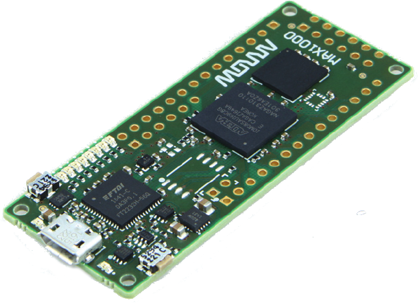
If you are looking for a low-priced FPGA board to get started with, the MAX1000 should fit the bill nicely. Indeed, it has just about all of the basic components within it that you should need to do FPGA work.
 |
It has an 8MB flash and, unlike the CMod S6 I worked with before, the MAX1000 actually has some decent RAM to work with – an 8MB SDRAM. These two items are the basics you will need for any soft CPU work you wish to do. Of course, you’ll also need an LED or two, and the MAX1000 has a nice complement of eight of them. The motion sensor on top is also fun bonus not normally found on most FPGA boards. Further, the motion sensor also contains an accelerometer capability, so a fun project might be to create an electronic level. Even better, the auxilliary A/D that comes as a part of this MEMS motion sensor chip will spare a lot of designers the need to integrate their own digitizer onto board.
While I’m not too excited about the 12MHz oscillator, an on-board PLL turns this nicely into a 100MHz clock for whatever your application might require.
You can even connect your own power supply to the board through its through-hole connectors, in case you wish to run from something other than USB.
Nice, huh?
So what’s missing? Your application. That’s why I said this has just about all of the basic components you will need. However, it has a nice host of GPIO through-holes, and even a place where you might solder in a PMod or perhaps just a PMod header.
What makes this even nicer? The price is only $30. This will make the board a nice entry board for hobbyists who aren’t sure they want to do more, and for classroom instructors who need to purchase a large number of boards to teach with. (You may need to teach soldering at the same time, since the board has only through hole connectors, however.)
The final item that I like about the board is the form factor. I don’t know, maybe it’s just me, but I tend to like really small FPGA boards. Perhaps its because they are easier to integrate into other applications. Perhaps it is some other reason. Either way, I love the form factor. Even if you don’t like small thin boards like I do, though, you will like the fact that there are very few bulky components to get caught on things and ripped off of the board.
Indeed, this board has the makings of being a very nice entry level FPGA board. No, you aren’t going to learn how to process video with this board. However, the possibilities of what you might do with the board remain limited more by your imagination and the size of the MAX-10 FPGA than anything else. What would you like to do with it?
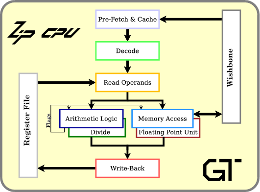 |
Personally? I might like to place a ZipCPU onto this board. I think I already have just about every thing I need for that. I’ve got a full featured QSPI flash controller, and even an SDRAM controller from another project. I should be good to go, right?
The Bad
While I love the MAX1000’s design and the opportunities built into the circuit board, and while the sales sheet looks beautiful, building with this board has already taken more work than I had expected. The primary difficulty I’ve had so far, other than the Ugly section below, has been finding the documentation.
The first part of working with any circuit board is always finding the documentation. This means finding a board’s schematic, its User Guide, and any data sheets for the parts on the board. In this regard, I may be spoiled by Digilent–their documentation is always found from a link on the sales page, and it is usually quite complete. For the MAX1000, however, I had to struggle for quite some time to find its documentation. I couldn’t find it linked anywhere from Arrow’s sales page, nor was their sales documentation anything I could build with. To make matters worse, searching Arrow’s data sheets was quite fruitless–and yet they are selling this board.
To spare you the trouble, I’ll post the links I finally found below. (Thank you Google.) The support for the MAX1000 comes from Trenz Electronic, who has built both a wiki page for the board, as well as hosting a forum for any problems you might have. Indeed, you can find these links from Trenz’s sales page for the MAX1000. (Well done Trenz!)
Hence, with a little work I was able to find the schematic and even a User Guide. From the schematic I could google the data sheet for any part on the board. Indeed, you’ll find many of the links within this article point to the data sheets that I was able to find.
The wiki also offered several example designs that I might use. However, as I looked through each of them, none of them had any HDL code–whether Verilog or VHDL.
Worse, although the schematic described what pins were connected to which part, and even described which pins were available for external connections, it offered nothing to tell me which pins corresponded to which GPIO’s.
For example, consider what the schematic has to say about the GPIO’s on the left and right sides of the board, shown in Fig 4.
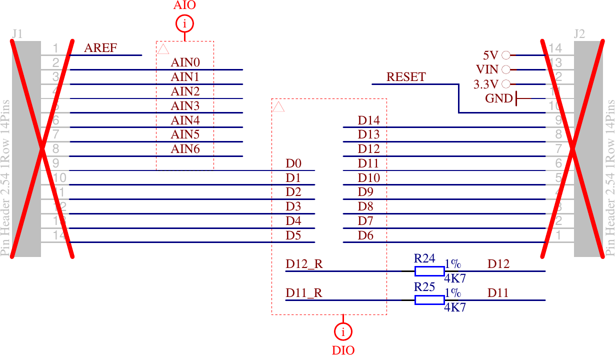 |
Now, looking at that figure, can you tell me which pins will be which? Are the pins on “top” the ones closest to the USB connector on the board? Are both rows organized in the same fashion? It doesn’t say. This means that I will need to spend time probing and reverse engineering just to orient the schematic to the board.
The problem isn’t limited to the two rows of GPIO pins. The schematic also has the same problem when describing the PMod port.
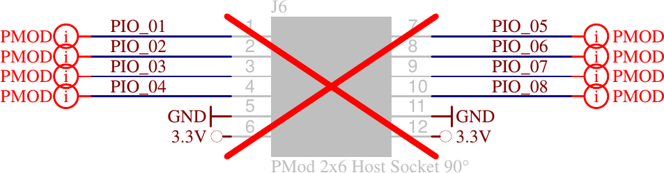 |
In both examples, the schematic makes it clear that the pins are available for use, but still leaves a lot for granted in how these pins are mapped to the actual device. For example, is pin 1 closer to the USB port, or is pin 5? Which side are the 3.3V and ground pins on, left or right? And which way constitutes “left” or “right”?
Perhaps I’m spoiled. I was considering connecting the MAX1000 to a Teensy LC, and looking at the Teensy LC’s I/O diagrams it was easy to correlate their physical I/O pins to both their I/O pin numbers and their associated functionality.
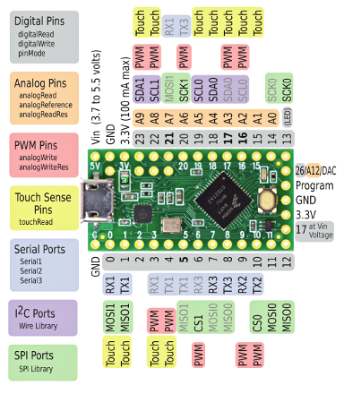
Unfortunately, the MAX1000 doesn’t have a simple picture showing how the pins are connected.
While such a diagram should be easy enough to create, I couldn’t find anything mapping pins to I/O’s on the board. The closest I could find were the (in order) pin numbers on the schematic for each of the headers. However, this wasn’t enough for me to determine header orientation, etc.
So while I like the hardware design and build, I’d strike a mark from the board for its (currently) poor documentation set.
The ugly
Okay, now for the really ugly part: I bought my MAX1000 only to discover on the wiki that they hadn’t finished building their Linux driver yet, so they hadn’t yet posted it for download.
Please, guys, can’t you hold off selling an item until the driver’s needed to support it are built and tested?
A month later, now, they finally have a Linux driver posted.
The problem is … it doesn’t work.
Sure, they have directions for installing their driver, directions which clearly tell you how to set it up. These directions have two problems.
-
First, they tell me that I need to disable (blacklist) the linux
ftdi_siokernel module. This is the very same kernel module that I am using quite successfully and extensively with my other FPGA projects. Blacklisting this kernel module will likely impact my other work in a negative fashion. -
If this wasn’t unworkable enough on its own, the second problem is that even after following their instructions I still couldn’t get Quartus’s JTAG loader to acknowledge that my hardware even existed. (See section 6.1.4 of the User Guide to know where this first failed for me.)
To make matters worse, neither the User Guide nor the Linux driver installation instructions offer any help in troubleshooting any potential problems.
My best guess is that there’s something missing in their instructions that they’ve overlooked, but I’m not sure what it might be. Perhaps they sold the device with the wrong EEPROM settings for the “USB blaster” (i.e. the FT2232).
The Redeeming
Here’s the really neat and redeeming part to this whole story: while the Trenz driver doesn’t work (yet), I can still configure my MAX1000 just fine using the open source libxvsf driver. No, it’s not point-and-click. No, I haven’t (yet) tried it with more than one device on my system–I need to experiment with that still. However, I didn’t need to blacklist my working FPGA serial port driver to use it.
To use this tool, you’ll want to download
libxvsf
and build it. I know there’s got to be an easier way to clone an svn
repository, but I ended up just copying the files in the repository one by
one to my computer. I then built the package using make all. In hindsight,
this is a bit of overkill since i only needed the xsvftool-ft232h program.
You will need to have the open source FTDI
library
and pthreads installed on your system.
I was a little concerned about whether this would work with the device I was using or not, so I then proceeded slowly for the next several steps—just to make sure I knew what I was doing (and so I didn’t destroy any of my hardware).
Hence the first thing I did was to unplug all of my other USB controlled FPGA devices. This probably isn’t technically required, but it does limit the number of things can go wrong.
I then issued a command to check the JTAG chain. I did this to get some
assurance that the tool worked as advertised. Since I already knew that my
MAX1000
had a USB ID of 0403:6010, this command was:
xsvftool-ft232h -D i:0x403:0x6010 -C A -cThe result was a rather cryptic error that xsvftool-ft2232h couldn’t open my
device. Hence, I quickly peppered the xsvftool-ft2232h.c code with
perror()
statements anytime an O/S call might fail. (Don’t you just love
open source?) As a result, I learned that I didn’t have the permission
to execute this command.
Next, I tried:
sudo xsvftool-ft232h -D i:0x403:0x6010 -C A -cand this seemed to work. The result was the simple line,
idcode=0x031820dd, revision=0x0, part=0x3182, manufactor=0x06e
After looking up the manufacturer’s ID code, I confirmed that 6e is indeed
the manufacturer code for
Altera. Further, Altera’s
JTAG documentation identifies that the 0x031820dd device is indeed the MAX-10
FPGA
I am working with.
Ok, so now I know I’m talking to the right chip.
I then tried reading the FT2232’s EEPROM from the device.
sudo xsvftool-ft232h -D i:0x403:0x6010 -C A -R ftdi.eepromThe result was an error that the EEPROM CRC didn’t match. (I may have to look into that some more.) However, the command also produced a file that, when dumped in hex, looked like:
0000000 01 08 03 04 10 60 00 07 80 fa 08 00 41 44 9a 0c
0000020 a6 24 ca 12 00 00 00 00 66 00 00 00 00 00 00 00
0000040 00 00 00 00 00 00 00 00 00 00 00 00 00 00 00 00
*
0000200
The third through sixth bytes of this file, 03 04 10 60, caught my
attention. Knowing that
FT2232
chips keep their USB identifiers in their
EEPROM
memory, I immediately recognized these bytes as the
USB ID of 0403:6010–exactly what I expected from lsusb, the udev
configuration file I was told to install, and more.
The next task was to load my MAX1000 with my just-built configuration. For this, I opened up the “Program Device” dialog, and clicked on “Create JAM, JBC, SVF or ISC File…” from the file menu.
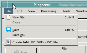 |
From here, I could save my design in the Serial Vector Format (SVF) libxvsf required.
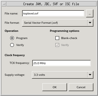 |
I then ran,
sudo xsvftool-ft232h -D i:0x403:0x6010 -C A -s quartus/toplevel.svfand my design loaded and worked!!
But perhaps I haven’t made clear the significance of this.
One common question on the Digilent forum is how to do things with the FT2232H FTDI chip on their FPGA boards. Digilent’s answer has always been that the circuitry and configurations associated with the FT2232 JTAG loader is a proprietary part of the board. For those who “accidentally” erase the firmware on their board, the issue is taken off forum and the poster is quietly given instructions (and software) to reload the firmware (i.e. the FT2232’s EEPROM).
However, using libxvsf, you can both read the firmware before playing with it, and you can (or at least should be able to) reconfigure it yourself. Want to see what the Digilent Arty FT2232H configuration looks like?
0000000 01 08 03 04 10 60 00 07 80 fa 08 00 00 00 9a 12
0000020 ac 28 d4 1a 00 00 00 00 56 00 01 00 c7 92 6a 35
0000040 51 01 00 02 41 72 74 79 00 00 00 00 00 00 00 00
0000060 00 00 00 00 00 44 69 67 69 6c 65 6e 74 20 41 72
0000100 74 79 00 00 00 00 00 00 00 00 00 00 00 00 00 00
0000120 00 00 01 00 00 00 00 00 00 00 00 00 00 00 00 00
0000140 00 00 00 00 00 00 00 00 00 00 00 00 00 00 00 00
*
0000200
If you do an od -c instead of an od -t x1 on the
Arty’s configuration file,
you get the following:
0000000 001  \b 003 004 020 140  \0  \a 200 372  \b  \0  \0  \0 232 022
0000020 254   ( 324 032  \0  \0  \0  \0   V  \0 001  \0 307 222   j   5
0000040   Q 001  \0 002   A   r   t   y  \0  \0  \0  \0  \0  \0  \0  \0
0000060  \0  \0  \0  \0  \0   D   i   g   i   l   e   n   t       A   r
0000100   t   y  \0  \0  \0  \0  \0  \0  \0  \0  \0  \0  \0  \0  \0  \0
0000120  \0  \0 001  \0  \0  \0  \0  \0  \0  \0  \0  \0  \0  \0  \0  \0
0000140  \0  \0  \0  \0  \0  \0  \0  \0  \0  \0  \0  \0  \0  \0  \0  \0
*
0000200
So, if I want to try my own FT2232H configuration and things don’t work out, I just need to return the device to this configuration.
It gets better.
Should you wish to build your own own design using the FT2232H chip, the MAX1000 schematic offers an example design, showing how to hook it up. As a result, there’s no need to ask for the proprietary portion of any Digilent schematic if you want an example. It’s already published for the MAX1000 as part of their schematic (see page 5).
This is all kind of nice and rather neat, but we aren’t done yet.
The FT2232H FTDI chip found on so many FPGA boards offers more than just a USB to UART interface mode. It also offers a USB to “Fast Serial Interface” mode. This is a simplex, bidirectional interface–with one direction of that interface shown in Fig 5 below.
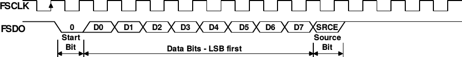 |
As you can see from the figure, this mode works much like a UART, with the exception of a clock that can run at up to 50MHz. That means that it should be possible to communicate to/from your board at 5MBps (that’s mega-BYTES per second), rather than the maximum UART rate which is about 200kBps (2MBaud). Even better, should you wish to play with this mode, the FT2232 datasheet provides all the information you need: from pin assignments to configuration and more.
Interested in a 25x speed increase anyone?
Conclusion
I suppose at the end of any review I should offer a recommendation: should someone buy this board or not? To that question I would answer that it depends upon the someone.
-
If you are willing to do some soldering, and you aren’t afraid of working without the best documentation then you might find this a nicely built, well-designed FPGA board to work with.
It certainly offers more capabilities than the CMod S6, at a much lower price point, although you will need to do some soldering if you want to connect the MAX1000 to a breadboard.
-
In a similar fashion, if you want to do some experimentation with the FT2232 interface found on many FPGA boards, the documentation and libxvsf should give you a clear enough starting point.
-
On the other hand, if you’ve never done any FPGA design before and just want a beginner’s board, this probably isn’t (yet) the board you want to start out with.
As for me, finding an open source FT2232 interface and schematic makes it all worth while. Indeed, I’m still drooling over the opportunity to fire up and test that 5MBps fast serial I/O link.
He that withholdeth corn, the people shall curse him: but blessing shall be upon the head of him that selleth it. (Prov 11:26)