
Project Ideas: PMod AMP2
 |
Someone recently contacted me to ask how to build a design for their PMod AMP2. My response to him was to provide a list of projects, from very simple to complex, of things he could do with his PMod AMP2. Indeed, I thought this list was so valuable and useful as a set of beginner projects, that I thought I might share it here.
Before starting, however, if you haven’t yet gone through my tutorial to learn how to use buttons and serial ports, and likewise how to simulate and use formal methods, you should do that first. You’ll need that background in a moment to keep things from going wrong.
0. Preliminary Steps
Before starting any project with an FPGA, or any other digital electronics project for that matter, there’s always a first step: gather the information you need. I usually create a project directory, and a subdirectory of that directory that contains these reference files. Specific files you will want to gather include:
-
The schematic for your board(s). This includes not only the schematic for your FPGA base or development board, but also the schematic for any peripheral boards you might wish to use.
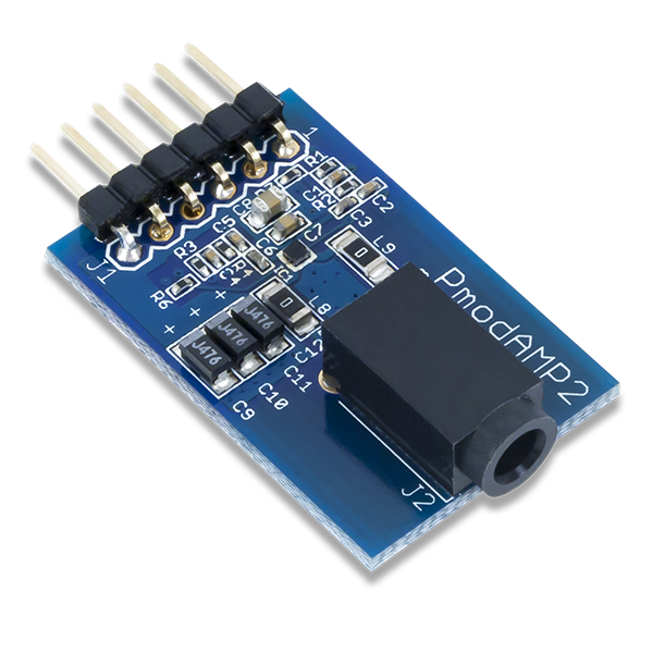
In this case, you would want a copy of the schematic for the PMod AMP2.
-
The data sheets for all of the parts on the board.
For this, you can usually work your way through the schematic to find the part IDs. On a good schematic, these will be listed–often next to the the various chips on the schematic. You can usually take the cryptic number and google it to get the data sheet.
In the case of the PMod AMP2, there’s only one IC on the board. This IC is marked with “IC1” (integrated circuit chip number one) and “SSM2377”. A quick google search for SSM2377 yields this data sheet for the Analog Devices Filterless, High Efficiency, Mono 2.5W class D audio amplifier.
-
Any other documentation for your board(s): user guides, reference manuals and so forth.
Over time, I have found Digilent to be really good with their documentation. Every device I have purchased from them has had a reference page, and the PMod AMP2 is no different. The page often has links to tutorials and example project code as well. There’s even a reference sheet, that you’ll want to print (to a file) for your records as well.
You’ll need these items during your subsequent design, and once your board gets old enough they’ll become hard to find. Projects vanish, links move, etc. Worse, if your board eventually gets replaced with another board, you may grab the reference material for the new board and not notice the difference. By grabbing this information first, before anything else, and by keeping a copy with your project, you’ll keep yourself from having this problem.
1. Pin Discovery
If you know your FPGA, or if you are an old hand at digital circuitry, you may be able to breeze through this step. For me, I’m always struggling to figure out which I/O pin on my board connects to which pin on an external peripheral. Mapping these together can be tedious, but it needs to be done carefully and done right to avoid any potential short circuits.
Often, a board will come with a master constraint file. (You did copy this in the first step when you bought your FPGA, board, right?) This will work for all of the on-board peripherals–except things with bidirectional names. For example, which direction does the “TX” wire go between your FPGA and another chip, such as an FTDI USB-UART chip? Does it “transmit” from the FPGA to the FTDI, or is it the “transmit” pin from the FTDI USB-UART chip to the FPGA?
This problem can be compounded by the Pmod you are working with, if the pins on the PMod aren’t well labeled.
Often, you can find a particular pin with a square pad. This is pin one, and it should help you figure out which schematic pin names map to which physical FPGA I/O pad.
From this, create/adjust your master constraint file. (Don’t forget to keep a copy of the original!)
You can do this the hard way too. Set a pin to be an output, and then drive the pin high. Use your voltmeter to then figure out which pin (or pins) is at the right voltage. You can then set the pin low and see which pin changes.
Or, you can do what one person did: Force each pin to be a serial port transmitter with a different message, and then take another board and read off the pin mapping from there.
2. Your first design: a voltage controller with no audio
We’ve discussed the PModAMP2 before. Perhaps you might remember that this was the design I demonstrated my “improved” PWM approach with. The board itself offers an analog lowpass filter, followed by an amplifier. The basic approach to sending “audio” to the board involves sending a high frequency signal whose proportion of 1’s to 0’s roughly matches the value of the audio sample you are trying to send.
For your very first design, skip the PMod AMP2, and just send your (would be) audio to the audio input pin of (what would be) the PMod AMP2s audio input port.
For example, you could set this port based upon a counter and a threshold.
	parameter [7:0] THRESHOLD = (some value);
	reg	[31:0]	counter;

	always @(posedge i_clk)
		counter <= counter + 1;

	assign o_audio = (counter[7:0] < THRESHOLD);
Set the threshold to 0, and then use your voltmeter. You should be able to read zero volts. You can often find a suitable ground for your voltmeter from the shield on the USB port. Sometimes the screws for any standoffs are connected to board ground. If all else fails, there’s a ground pin on the PMod connector itself–just don’t accidentally fumble finger your probe and cross-connect that pin with the power pin right that’s next to it. I’ve often found that sticking a wire (or wires) inside the PMod port itself gives me better access to the pins when making measurements like these.
Now try setting the threshold to 8'hff. You should be able to read something
close to 3.3V. Now try 8'h80, 8'h20, and 8'hc0.
3. An adjustable controller, but still no audio yet
Before trying this next step, make certain you have a solid understanding of debouncing and why it’s necessary. I’m going to assume you have four switches to your board, and that their outputs have been suitably debounced and synchronized to your system clock. Buttons would work as well, if you have enough fingers to push them and hold your voltmeter.
If you have enough switches/buttons, why not adjust your design so that the threshold from the last step is now variable? We’ll test the design using the voltmeter here again.
For example, your design might now contain something that looks like:
	always @(posedgde i_clk)
	casez(i_sw)
	4'b1???: threshold = 8'h44;
	4'b01??: threshold = 8'h88;
	4'b001?: threshold = 8'hcc;
	4'b0001: threshold = 8'hff;
	default: threshold = 0;
	endcase

	always @(posedge i_clk)
		o_audio <= (counter[7:0] < threshold);
Notice that, to do the last comparison right, o_audio must be declared as
an output reg o_audio instead of output wire o_audio.
4. Your first sound
If you’ve gotten this far, then it’s time to try a sound to see if it works.
Are you ready to plug in your board? Don’t forget to hold the SHUTDOWN pin
high (inactive). You might want to leave the gain low initially, or even
control it from a button.
	assign	o_shutdown_n = 1'b1;
	assign	o_gain = debounced_button;
Let’s send a tone to this board. It won’t be a nice tone, it won’t be a pretty tone, but it will at least let you know that your PMod AMP2 works and that you have the PMod pins wired correctly.
To do this, we’ll go back to the counter, and adjust its step size based upon
your board’s CLOCK_FREQUENCY_HZ and your desired TONE_FREQUENCY_HZ.
(You’ll need to look these up and set them appropriately yourself.)
	parameter	COUNTER_WIDTH = 32;
	localparam	MSB = COUNTER_WIDTH-1;
	parameter STEP_SIZE = (1<<(COUNTER_WIDTH))
				* TONE_FREQUENCY_HZ / CLOCK_FREQUENCY_HZ;

	reg	[COUNTER_WIDTH-1:0]	phase;

	always @(posedge i_clk)
		phase <= phase + STEP_SIZE;

	always @(*)
		o_audio = phase[MSB];
But what TONE_FREQUENCY_HZ to start with? How about 440.0Hz? This is the
frequency of the basic tuning A in the first octave above middle C that
many instrumentalists will use to tune their instruments
with. Want to go up an
octave?
Double the TONE_FREQUENCY_HZ. Want to go down an
octave?
Halve it.
If you haven’t been simulating your designs, now is a good time to start. The problem you’ll have is that you might struggle to “see” the output waveform. Not a problem, take a box car filter and filter your signal until it looks reasonable in GTKWave. You may need to filter it several times over.
5. A prettier sound
The problem is that a square wave just doesn’t sound all that pretty on the ear. Can we do any better?
Sure we can! Let’s use a table lookup based sine wave. A basic 8-pt table shouldn’t be too difficult. You can find a discussion about how to build one of these here, and an example program that does this and more here. Once you have the table, your audio logic will now look something like:
	wire	[7:0]	sample;

	sintable tbl(i_clk, phase[MSB:MSB-9], sample);
To get a nice quality 8-bit sample output, lets run it through the “improved PWM” method we’ve already discussed.
	wire	[7:0]	offset_sample;
	assign offset_sample = { !sample[7], sample[6:0] };

	reg	[7:0]	pwmcounter;
	wire	[7:0]	brevcounter;

	always @(posedge i_clk)
		pwmcounter <= pwmcounter + 1;

	integer k;
	always @(*)
	begin
		for (k=0; k<8; k=k+1)
			brevcounter[k] = pwmcounter[7-k];
	end

	assign	o_audio = (brevcounter < offset_sample);
You should now have a nice quality sounding tone coming out of your device.
You may find it to be obnoxiously loud, however, and this design gives you no control of the amplitude (volume). So, let’s adjust the amplitude.
6. Adjustable Volume
If you have hardware that will support multiplies (Xilinx, Intel, ECP5, some ice40s, etc), then volume adjustment is easy. Simply multiply by the chosen volume, and shift right.
	parameter [7:0]	VOLUME = 3'h1f;
	reg	[15:0]	sample;

	always @(posedge i_clk)
		sample = sinesample * VOLUME;
You can even use the buttons / switches as before to adjust the volume, just as we did when adjusting the voltage earlier.
But what if you have an iCE40 hx8k, or 1k FPGA with no internal hardware multiplies? How will you then adjust the volume?
In this case, the easy way is to shift your sample by some power of two.
	reg	[2:0]	volume;
	// Set your volume register somehow ...
	// Then,
	always @(posedge i_clk)
	case(volume)
	3'b000: sample = 0;
	3'b010: sample <= { {(6){sinesample[7], sinesample[7:6] };
	3'b010: sample <= { {(5){sinesample[7], sinesample[7:5] };
	3'b011: sample <= { {(4){sinesample[7], sinesample[7:4] };
	3'b100: sample <= { {(3){sinesample[7], sinesample[7:3] };
	3'b101: sample <= { {(2){sinesample[7], sinesample[7:2] };
	3'b110: sample <= { {(1){sinesample[7], sinesample[7:1] };
	3'b111: sample <= sinesample;
	endcase
Voila, coarse grained volume control!
7. Swept Tone
Did you know that if you adjust the phase step on every sample, the tone will sweep up or down?
initial	phase_step = 0;
always @(posedge i_clk)
	phase_step <= phase_step + 1;

always @(posedge i_clk)
	phase <= phase + phase_step;
The curious thing about this design is that the frequency will sweep up, much like you expect, but then it will start sweeping back down!
Try it! Can you explain why?
8. Adjustable Frequency
 |
With a little bit of work, and some table lookups, we can adjust the output frequency as well.
For example, there are eight notes in a scale. If you check Wikipedia’s
piano key frequency
page, you’ll discover the frequencies
of a scale in the key of C are: 261.6,
293.6, 329.6, 349.2, 391.9, 440.0, 493.9, and 523.25. Why not
create a design that steps through these output frequencies at two per second?
You’d need a half second timer.
	parameter HALF_SECOND_STEP = (1<<33) / CLOCK_FREQUENCY_HZ;

	reg	[31:0]	half_second_timer;
	always @(posedge i_clk)
		{ half_second_stb, half_second_timer }
			<= half_second_timer + HALF_SECOND_STEP[31:0];
You’ll also need a state machine, running from 0 to 8 and back again to
capture the pitch number of interest:
	always @(posedge i_clk)
	if (half_second_stb)
	begin
		fsm <= fsm + 1;
		if (fsm == 8)
			fsm <= 0;
	end
You’ll then need a table lookup, to get the values you want:
	parameter [31:0] STEP_C = (1<<(COUNTER_WIDTH))
				* 261.6 / CLOCK_FREQUENCY_HZ;
	parameter [31:0] STEP_D = (1<<(COUNTER_WIDTH))
				* 293.6 / CLOCK_FREQUENCY_HZ;
	// ...
	parameter [31:0] STEP_OCTAVE = STEP_C * 2;

	always @(posedge i_clk)
	casez(fsm)
	4'h0:	phase_step <= STEP_C;
	4'h1:	phase_step <= STEP_D;
	4'h2:	phase_step <= STEP_E;
	//
	4'h7:	phase_step <= STEP_B;
	4'h8:	phase_step <= STEP_OCTAVE;
	default: phase_step = 0;
	endcase

	always @(posedge i_clk)
		phase <= phase + phase_step;
Now that you have various states, it’s a good time to make certain you are both formally verifying and simulating your design before it goes onto your board. Your ears will thank you.
9. Playing a simple song
We now know all of the parts necessary to play a simple song: You can play notes, coarsely adjust their volume, adjust their frequency, and more. Why not turn this into a song?
You can, if you use a block RAM memory. Remember using memories from our tutorial? Let’s create a block RAM memory describing the volume and pitch of every point in this song.
	initial	rd_addr = 0;
	always @(posedge i_clk)
	if (half_second_stb)
		rd_addr <= rd_addr + 1;

	initial $readmemh("song.hex", songmem);
	always @(posedge i_clk)
		{ volume, frequency_step } <= songmem[rd_addr];
At this point, I’m sure you will find anything and everything going wrong as
you try to create your songmem memory. You are testing everything in
simulation first,
right? You should be able to generate an audio file and “listen” to your
song before you place it on your board–or you might never figure out why your
board is or isn’t working. If you aren’t familiar with
SoX
it could easily be your good friend during this process.
10. Playing some harmony
Now that you can play one audio file, why not two? Why not two, three, or even four-part harmony? To create four-part harmony, you’ll need four phase counters, and varying step sizes according to the frequency of each. (Be careful not to place two notes at the same frequency! You might not hear one or the other.)
Each of these phase counters will then go into the sine wave lookup table, just like before.
The next big difference is that we’ll take the outputs of the sine wave lookup and create our final sample from their sum.
	always @(posedge i_clk)
	begin
		uppers <= soprano + alto;
		lowers <= tenor + bass;

		sample <= uppers + lowers;
	end
The problem with the above approach is bit accumulation. The sum of two 8-bit numbers requires 9-bits, and the sum of two 9-bit numbers requires 10 bits. You’ll want to make certain that you don’t “clip”, or distort your sound, as you add these voices together. Of course, this might also adjust your audio when only one voice is output, so that’s another thing to adjust.
11. Playing a sampled audio file
All of the above is great if you want to play sounds that come across like computerized beeps, squeeks, chirps, and mary had a little lamb, but somehow our four-part harmony, just didn’t quite sound right.
What went wrong?
The list is numerous. Human voices don’t hold constant pitches, they vibrate in frequency near the right one. When they move from one frequency to another, they do so gradually. Volume comes in many shades, crescendos and decrescendos are gradual, and I could go on.
You might try interpolating between frequencies and volumes. How about quadratic? You might find that interpolation helps, but you might also want to do so at a faster step size than 2Hz.
While I would challenge and encourage anyone to continue this thread, I’d also like to offer some other ideas.
 |
FPGAs often have on-board block RAM, such as the iCE40 hx8k which has 8kB of RAM. If we filled that RAM with 8-bit sampled audio values, we could move from one sample to the next at 8kHz and play about a second of any sound.
That’s enough for some recognizable doorbell’s, and perhaps even for Homer to shout, Doh!
How about using the flash device found on most FPGAs to hold your audio samples? We discussed how to build a basic controller for a flash device some time ago. If you chose to write audio samples to that device, reading those samples from that device later should allow you to play any sound you want. Even better, since your typical flash device holds about 16MB, that should be enough to hold a half an hour of sampled audio.
The only thing is … once you get this far, the project becomes a big enough challenge that I can’t tell you how to do all of the pieces in the few lines we have left below.
12. CPU audio
If you have any interest at all in using a soft-core CPU on your FPGA, this may be the time to try it. There’s many ways to do CPU based audio, but I’ll warn you: It’s not as easy as it looks.
You’ll need to build an audio device with a bus interface. You can control each sample, by having the CPU write a sample value to this device. You may also wish to place a FIFO in your audio device as well.
Here are some of the approaches you can try:
-
Have the CPU poll the audio device. Wait in a tight loop, reading from the audio device’s control register(s), until you read from the audio device’s control register a value telling you it needs a new sample, and then feed it one. Repeat while you have samples left, then set the device to zero.
-
Interrupt driven audio. By this I’m referring to something very similar to the polled approach above, only this time don’t wait in the tight loop. Either put the CPU to sleep waiting on an interrupt, or go on and do something else. Then when an interrupt occurs, reset the interrupt line and feed the audio device a new sample.
-
There is so much to be learned in this exercise. For example, interrupt driven audio at 8kHz while doing something else might require more cycles than your CPU has. One way to deal with this is to place a FIFO into your audio driver, and only interrupt when the FIFO is half empty. You can then send a half-FIFOs worth of information to the audio driver and go back to what you were doing.
-
You may find that interrupt driven audio is still too slow for what you need to do. In that case, why not use a DMA engine, and teach the DMA engine to fill the audio driver with samples every time the FIFO gets below some watermark?
One of my earlier ZipCPU projects involved “ringing a doorbell” from the FPGA, by having it play a sampled doorbell audio sound through the PMod AMP2. In my case, the CPU was running from flash, and really struggled to keep up with interrupt driven sample by sample audio. I learned a lot by learning how to place some of my software in flash, other parts in block RAM, and then how to create a basic software “pipe” so the audio “program” didn’t need to perpetually fill the (software) FIFO.
It was a fun exercise for me, and a challenge for a Spartan 6 LX4 of all devices.
Conclusion
If you’ve never worked with an audio peripheral before, there’s a lot you can learn about by doing so. I/O connectivity, Pulse-Width Modulation, sinewave table lookups, frequency, volume, harmony, interpolation, and more–the list just goes on. There’s lots of stuff to learn here, and the example projects suggested above are just the bare beginnings of what you might do.
I’ll admit, this article doesn’t follow my usual style. Usually, I like to write articles about how to perform some task, or build some element. I describe the task, walk through an outline of it, then through the code and formal properties. While I’ve tackled some fairly complex problems in this fashion on the ZipCPU blog, it often leaves beginners wondering where to start to try things myself. So, I thought a list of baby steps from nothing to something significant, like the steps above, might be useful.
Let me know what you think. (I also recommend fpga4fun.com for picking up fun/sample projects.)
The one big thing missing from the discussion above is the debugging bus. I personally struggle to build designs at all without some form of debugging bus allowing me access into the registers within a given design. This is how I go about programming Flash devices, loading programs into the CPU, and more. It’s also how I normally go about debugging any FPGA, projects I’m working on that pass formal verification and simulation, but still don’t quite do what I want.
I skipped the debugging bus, however, since the individual who originally asked the question of me had a GO board. The GO board only has a rough 1k LUTs, and you may find it a challenge to place a debugging bus into 1k LUTs. It’s not impossible, but it’s not going to be easy either.
I look forward to hearing from you: would you like more of these project lists, going from scratch to a simple capability with a particular piece of hardware?
Also I heard the voice of the Lord, saying, Whom shall I send, and who will go for us? Then said I, Here am I; send me. (Is 6:8)