
How to eliminate button bounces with digital logic
The fundamental way to avoid FPGA Hell is to start from a small design and to build to a more complex design one small piece at a time. You might even call this good engineering process. Along the way, you’ll want to avoid changing too many things at once. Lest, if you introduce too many changes at the same time, you’ll never know which change is keeping your design from working. Hence, your goal should be to build your complex designs from an initial simple design, modified by only simple changes.
The corollary to this rule is to make certain that your test and debug infrastructure, I like to call this your scaffolding, is never one of multiple unknowns within your design. There is a time for testing the scaffolding of your design: before you need it. You want to be convinced in the reliability of your scaffolding before you ever commit your time and design to its strength.
This has a particular application when you wish to use the buttons, switches, or keypad entry mechanisms to your design. My advice? Don’t use them as part of your debug infrastructure until you have proven that they work the way you want them to work first. The reason is that buttons bounce, and creating a signal that doesn’t bounce requires digital logic.
What makes a button debouncing circuit particularly unique when it comes to debugging, is that it is difficult to test apart from using a real button. You just can’t simulate an unknown piece of hardware’s response very well. This is what makes the coupling of the debugging bus and wishbone scope so powerful: using them, you can not only measure what’s going on any time a button gets pressed, but you can also measure whether or not your debouncing logic works within that context.
In this article, we will examine how to debounce a set of button inputs, so that they can then be used as part of your test infrastructure.
Generating Events
User inputs, whether they be button presses, switches, or other, can be a very valuable part of your design. They can be used to reset your board, to start a test, or even to enter data into your design. Indeed, once you cut the umbilical (JTAG, UART, or debugging bus) to your board, such inputs may be the only means you have remaining of controlling your board.
To understand how valuable these inputs can be, consider the following scenarios where student’s have tried to use a button:
-
One student thought it would be nice to create a design that prints Hello World anytime a button is pressed.
This student hadn’t yet gotten his first serial port to work. By adding the button processing to his design, he added an additional unknown to the design and was thus unable to discern which piece of logic was failing when the whole didn’t work.
-
Another student’s challenge was to increment a counter every time a key was pressed. [1]
This sounds easy, right?
This student was surprised to discover that every time he pressed a button, his counter jumped by more than a single count. He was expecting a single state change only. Indeed, his design depended upon being able to detect singular button press events. The multiple detected events “broke” the design he was building.
While both of these applications are valid applications of a button, both students ended up stuck with an FPGA design that didn’t work because they weren’t aware of the difficulty associated with buttons: they bounce.
Turning a button from a bouncing electrical signal into a useful entry method requires some debouncing logic.
Metastability, and avoiding the beginner’s mistakes
Before we dig deeply into how to debounce a button, let’s take a quick moment to mention how not to work with a button.
The beginner is often enticed by the capabilities of a chip to transition on a positive edge. Hence, I’ve seen many beginners start their approach with
initial	event = 1'b0;
always @(posedge i_button, posedge i_reset)
	if (i_reset)
		// Reset our system whenever i_reset is true
		event <= 1'b0
	else
		event <= 1'b1;
The same mistake can be manifest in an attempt to count events, as in:
initial	event = 1'b0;
always @(posedge i_button, posedge i_reset)
	if (i_reset)
		counter <= 0;
	else
		counter <= counter + 1'b1;
Both of these approaches to measuring buttons are problematic.
Here’s why:
-
Timing:
i_buttonis not a clock. Your tool-suite will struggle to analyze the timing between when a button press event takes place and the rest of the logic within your design. It’s going to try to optimize the distance (in time and space) between the button press logic taking place and the logic that depends upon it, and since the button press wasn’t a clock the result will be difficult to analyze. The result will be unreliable logic in the rest of your circuit. -
Asynchronous reset’s tend to have a propagation delay when they work their way through your circuitry. Therefore, they may reset one portion of your circuitry before another. While this might not be such a problem if every part of the circuit gets reset eventually, this doesn’t mitigate the exit from the asynchronous reset . Hence, when using an asynchronous reset, you may find some pieces of logic are released from reset before other pieces of logic. (This is bad)
Particularly problematic are spurious reset signals that last for less than a clock interval, perhaps created by some radio frequency interference within the FPGA board’s environment. These signals may partially but not completely reset an FPGA’s logic.
The beginner’s reset rule: Just avoid the asynchronous reset. This is easily done by removing
posedge i_resetfrom the dependency line in the always block.
Given this information, let’s try to build our logic again:
initial	down  = 1'b0;
initial	event = 1'b0;
always @(posedge i_clk)
	if (i_reset)
	begin
		down  <= 0;
		event <= 0;
	end else begin
		down <= i_button;
		event <= (i_button)&&(!down);
	end
This approach, while better than the first one, is still problematic.
While this avoids the asynchronous reset, it now has a problem with
metastability.
Specifically, i_button may not have settled for enough time prior to the
clock to create a stable logic signal. As a result, the down register may
be indeterminate. Some parts of your circuitry may decide down is true,
while other parts deciding down is false. You may get two events in a
row, or no events at all.
To avoid these problems, stick to these rules:
-
Use the positive edge of a single clock for all of your logic. I like to use the same basic clock wire,
i_clk, within all my modules for this purpose. Thei_clksignal itself is either externally generated, or the result of a PLL applied to an external clock signal. -
For any logic inputs that are not created synchronously to your clock, such as your button inputs, clock them through a pair of flip flops (example below). This applies to all external user input devices, such as buttons, switches, and keypad entry. This rule also applies to all of your external asynchronous inputs as well: PS/2 devices, UARTs, or indeed any wires coming from external circuits that do not share your clock.
While this alone doesn’t solve the problem of bouncing, it will make actually dealing with it a lot easier.
Using these rules, we can create a clock synchronous button input. The first step is to run the button input through two flip-flops to avoid any metastability issues.
initial	sync_pipe      = 1'b0;
initial	r_button_state = 1'b0;
always @(posedge i_clk)
	{ r_button_state, sync_pipe }
		<= { sync_pipe, i_button };
r_button_state has now gone through two flip flops from i_button, and so
it will be a one or a zero to all logic within your FPGA. Now that the
button input has been synchronized to our clock, we can detect when the
button input changes with such simple code as:
initial	r_last         = 1'b0;
initial	r_button_event = 1'b0;
always @(posedge i_clk)
begin
	r_last <= r_button_state;
	r_button_event <= (r_button_state)&&(!r_last);
end
The nice part of this technique for generating r_button_event, is that it
will only ever be true once for every time the i_button goes from off to
on.
The other common piece of logic drawn from an external button input is a
counter. Let’s assume that our reset input, i_reset is synchronous–perhaps
you created it via the dbgbus
infrastructure we’ve already
built. We can
use that input to increment our counter, and then we can use the button event
we just created to increment a counter:
always @(posedge i_clk)
	if (i_reset)
		counter <= 0;
	else if (r_button_event)
		counter <= counter + 1'b1;
At this point we’ve only solved the problems with metastability, the asynchronous clock, and synchronizing the button input to our clock. Now that we know how to avoid these mistakes, let’s debounce this button.
A Very Simple Debouncer
The basic approach to debouncing a button is to prevent the button’s output
from changing more than once every N clocks. Hence, we’ll build our
approach to debouncing around a timer, timer, that simply counts down to
zero. Any time this timer reaches zero, the current value will be forwarded
to the output. Further, we can control the time interval by just adjusting
the number of bits in the timer. We’ll call this number of bits LGWAIT.
Given those goals, here’s the code for a very simple digital logic debouncer:
initial timer = {(LGWAIT){1'b1}};
always @(posedge i_clk)
	timer <= timer - 1'b1;
always @(posedge i_clk)
	if (timer == 0)
		o_debounced <= r_button_state;
This approach should be good enough for most uses, so if you just want a very simple debouncing circuit this one will work.
However, if the latency in reporting the button press is important to you,
this piece of logic may cause the button press indication to wait for up to
2^(LGWAIT) samples before being reported. This problem is shown in Fig
1 below.
 |
This figure shows a “slow timer” in its top line. Any time the timer
finishes counting down, the slow timer line changes as a visual reference.
Notice then how the button press needs to wait on a transition in
slow timer (timer == 0) before it reports a button press?
That latency is what I’m talking about.
So, let’s return to this concept and see if we can’t do any better.
A Debouncer with more Immediate Results
This time, let’s rebuild this debouncing circuit around the idea that a
pressed button should be reported immediately, but that following changes
should be held off at least N=2^(LGWAIT) clocks after that. Fig 2 captures
this concept.
 |
In this approach, the timer starts when the first change is detected. While the timer is counting, changes are not permitted. As a result, the latency should be much lower than before.
We’ll follow some of the lessons from our post on how to minimize
logic resources.
In particular, we’ll use a second register, ztimer, together with our timer.
This register will be a single wire only, and we’ll set it to true any time
timer is zero. Finally, as we are going to set this up, any time ztimer
is true the circuit will be responsive to a changing signal.
So here’s the code for the timer and ztimer:
initial	ztimer = 1'b1;
initial	timer  = 0;
always @(posedge i_clk)
	if ((ztimer)&&(different))
	begin
		timer  <= {(LGWAIT) {1'b1} };
		ztimer <= 1'b0;
	end else if (!ztimer)
	begin
		timer  <= timer - 1'b1;
		ztimer <= (timer[(LGWAIT-1):1] == 0);
	end else begin
		ztimer <= 1'b1;
		timer  <= 0;
	end
The count-down will begin any time the timer is at zero (ztimer is high),
and the inputs are different from what they were. (We’ll come back to this
in a moment.) Once the timer is running, it will count down to zero.
When it hits zero, it will hold there until another change has been detected.
As mentioned above, we’ll use the register different to signal any time the
input is different from the output of our debouncing circuit. different,
though, will then need to remain true until any ongoing countdown completes.
Hence, as long as different gets set, either when the timer isn’t counting
or between count-downs, different will make sure that the timer restarts
again.
always @(posedge i_clk)
	different <= ((different)&&(!ztimer))||(r_in != o_debounced);
We now finally have all the pieces necessary to create our low-latency
debounced output. This output will be set to whatever we just finished
reading, but only ever anytime ztimer is set.
initial	o_debounced = { (NIN) {1'b0} };
always @(posedge i_clk)
	if (ztimer)
		o_debounced <= r_last;
Notice the choice to set o_debounced any time ztimer is true, coupled with
the fact that ztimer idles at zero. Because of this, any time a button is
pressed (or released), while the circuit is idle (ztimer is true), will
immediately adjust o_debounced with the new value. Subsequent bounces,
until the signal becomes stable again, will be limited to only change every
2^LGWAIT clocks.
Now, if we go back and review some of the button presses from the opening post on debouncing, you’ll be able to understand the debounced trace in Fig 3. below.
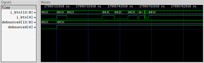 |
In particular, notice how the debounced trace changes immediately as soon
as the button is pressed, and before it is done bouncing. It doesn’t change
again until all the bouncing is over, and the user releases the button.
This demonstrates that our logic actually worked.
Conclusion
While this post presents working debouncing
logic, the
task remains far from complete. For example, how many bits (LGWAIT) need
to be allocated to the counter? Not quite so subtle is the question of how
shall this capability be proven? In particular, this logic requires
an external button input bounce in order to properly verify its functionality.
Our next post, therefore, will focus on how to measure bounces so we can tell if a bounce has taken place. After that, we’ll discuss how to modify the debugging bus for this purpose, and to get a trace from within the design so we can see what’s going on. Then we’ll go and move on to the next topic.
Can the Ethiopian change his skin, or the leopard his spots? then may ye also do good, that are accustomed to do evil. (Jer 13:23)