
Using Sequence Properties to Verify a Serial Port Transmitter
For those who have been reading this blog, you’ll know that most of my formal work has involved the immediate assertion subset of the SystemVerilog Assertion language. I’d like to take this opportunity to discuss some of my frustrations using SVA sequences, and illustrate how I was able to replicate much of the functionality I needed from SVA sequences with immediate assertions alone.
For this discussion, we’ll use the example of a serial port transmitter I built long ago.
The First Serial Port Transmitter
One of my early Verilog projects after starting Gisselquist Technology, LLC was to build a serial port.
I’ve only learned later, at ORCONF2017 to be exact, that building a serial port is highly controversial. At issue is, why should anyone rebuild the wheel? There are so many serial ports available on line, examples to look at, etc., that some would argue that it hardly makes sense to build one more. The “market” is quite saturated.
I also discovered, long after implementing my own serial port “the right way” that there’s a well established interface between a computer and a serial port based upon the 16550 serial port. Of course, mine was done “right” from the beginning just because it was mine–we need not go over all of the flaws with that logic today, but there is something to be said for having pride in your own workmanship. On the other hand, I’m sure we can all be critical of an interface that takes multiple steps to configure, and that even requires paging in and out bytes of data. We can also be highly critical of a buggy implementation that can be caused to send data that it was never commanded to sent. (It’s amazing what a little bit of formal verification can find …)
Yes, I have enjoyed the reality that my own serial port can be completely configured by writing one 32-bit word to the configuration register, as shown in Fig 1.
 |
Hence, in one 32-bit write you can configure:
- The baud rate, specified as an
integer divider of the clock. This integer divider is shown in Fig. 1 as
Baud CLKS - Whether or not hardware flow control is to be used, shown in Fig. 1 as
H. - Whether the serial port would transmit 5, 6, 7, or 8 bit characters. These
are the
Nbits in Fig. 1. - The parity bit, which can be
either no parity, even or odd parity, or even mark or space fixed parity
values–as specified by bits
P(use parity),F(fixed parity) andT(type of parity). - If the stop bit is a single stop bit, or rather two stop bits. This is
specified by bit
Sin the setup register.
A separate write to the data register could send a break condition down the line.
But why did my serial port need all this functionality? Well, ahm, … it didn’t. It only needed it because I wanted to build a full featured serial port. Hence, I implemented every feature that a serial port could or should have.
Why not? Coding is fun, right?
Sure, but does it work?
Well, I tested the 8 bit character, with one stop bit and no parity at a variety of baud rates. That worked quite well.
… and this is the problem with a lot of both open and closed source digital design these days.
It’s one thing to design something that’s easy to do because it’s fun. It’s something else entirely to fully verify that all of this (cough unused) functionality even works. Indeed, the greater the functionality, the greater the number of modes something has, the more complex the verification problem becomes. How did I know that the design would work if I later asked it to operate in a mode I had never tested nor verified? I didn’t. Worse, when such a time would come later, I’d likely be trying to verify something else and not expecting a bug in a “working” serial port component.
This is neither black box nor white box verification. It is ticking box verification.
But the story goes on.
The Simplified Serial Port Transmitter
The first problem I had with my one-size fits all serial port was that it
wouldn’t fit in a small
design. It just had way too much
logic.
So I simplified it. Since I only ever used one baud
rate, I created a parameter to fix the
number of clocks per baud to a constant
value. Since I only ever used 8-data bits, 1 stop bit, and no
parity–a protocol sometimes called
8N1,
I removed all of the other functionality from the core.
These simplifications lead to my txuartlite and rxuartlite serial port cores.
At one time, I was scrounging for logic elements so hard that I even parameterized the number of bits in the integer clock divider. Perhaps 24-bits was too many. Yes, design space has been tight.
These two cores became a mainstay of many of my designs–especially if I was
going to use a fixed baud rate with an
8N1,
protocol. How often was that? Essentially all the time.
But I said this article was about sequences, so let’s move on to formally verifying my lite transmitter core with some SystemVerilog sequences. Once you see how easy and awesome these sequences can be, we’ll then transition to looking at the fully functional transmitter implementation, and discuss how sequences can be used to verify it.
Verifying the Simplified Transmitter
If you want to know how to build a serial port yourself, this probably isn’t the article for you. Check out my tutorial instead.
If you want to know how to verify the receiver, then I’ll caution you that the proof of my my lite receiver isn’t trivial. It’s an asynchronous proof that involves two separate clock domains–one for the receiver and another subtly different clock for the (assumed) transmitter. The proof of this receiver was one of the more challenging proofs I have done–so there’s little likelihood I can fit it into this blog article. You are more than welcome to check out the code and formal properties yourself if you would like.
No, today we’re going to discuss the serial port transmitter. I’m also going to assume you know how to build a serial port transmitter, and so I’m only going to discuss a couple of details associated with the implementation.
First, the serial port transmitter is built around a state machine. This state machine has ten separate states:
`define	TXUL_BIT_ZERO	4'h0
`define	TXUL_BIT_ONE	4'h1
`define	TXUL_BIT_TWO	4'h2
`define	TXUL_BIT_THREE	4'h3
`define	TXUL_BIT_FOUR	4'h4
`define	TXUL_BIT_FIVE	4'h5
`define	TXUL_BIT_SIX	4'h6
`define	TXUL_BIT_SEVEN	4'h7
`define	TXUL_STOP	4'h8
`define	TXUL_IDLE	4'hf
I’ll probably adjust these in due time so that they are defined by localparams
instead of macros, but these are the state names today. Notice how there are
nine transmitting states and an idle state, and that they aren’t all sequential.
The second thing to note is that my design has a basic clock divider, kept in two parts. First, there’s the countdown clock. The logic below has been simplified, but you should get the idea.
	initial	baud_counter = 0;
	always @(posedge i_clk)
	begin
		if (state == `TXUL_IDLE)
		begin
			baud_counter <= 0;
			if ((i_wr)&&(!r_busy))
				// Start transmitting a new byte
				baud_counter <= CLOCKS_PER_BAUD - 1'b1;
		end else if ((baud_counter == 0)&&(state == 4'h9))
			// Transmission is finished
			baud_counter <= 0;
		else if (!baud_counter != 0)
			// Count down the number of clocks in a baud
			// interval
			baud_counter <= baud_counter - 1'b1;
		else
			// Start the next baud interval for the next
			// start, data, or stop bits
			baud_counter <= CLOCKS_PER_BAUD - 1'b1;
	end
Second, there’s the zero_baud_counter value. This is a registered
value designed to be equivalent of baud_counter == 0. As a reminder,
if you ever find yourself drafting code to do something like this, you’d
want to place a reminder in your draft code to,
	always @(*)
		assert(zero_baud_counter == (baud_counter == 0));
Finally the design has a basic state machine,
	initial	r_busy = 1'b1;
	initial	state  = `TXUL_IDLE;
	always @(posedge i_clk)
	begin
		if (!zero_baud_counter)
			// r_busy needs to be set coming into here
			r_busy <= 1'b1;
		else if (state > `TXUL_STOP)	// STATE_IDLE
		begin
			state <= `TXUL_IDLE;
			r_busy <= 1'b0;
			if ((i_wr)&&(!r_busy))
			begin	// Immediately start us off with a start bit
				r_busy <= 1'b1;
				state <= `TXUL_BIT_ZERO;
			end
		end else begin
			// One clock tick in each of these states ...
			r_busy <= 1'b1;
			if (state <=`TXUL_STOP) // start bit, 8-d bits, stop-b
				state <= state + 1'b1;
			else
				state <= `TXUL_IDLE;
		end
	end

	assign	o_busy = (r_busy);
shift register,
	initial	lcl_data = 8'hff;
	always @(posedge i_clk)
		if ((i_wr)&&(!r_busy))
			lcl_data <= i_data;
		else if (zero_baud_counter)
			lcl_data <= { 1'b1, lcl_data[7:1] };
and output bit.
	initial	o_uart_tx = 1'b1;
	always @(posedge i_clk)
		if ((i_wr)&&(!r_busy))
			o_uart_tx <= 1'b0;	// Set the start bit on writes
		else if (zero_baud_counter)	// Set the data bit.
			o_uart_tx <= lcl_data[0];
None of this should look strange to you. If it does, please check out my tutorial for a discussion of how to build a serial port and why.
I’m just presenting this as a quick background, because I’d like to discuss the sequences used to verify this core.
Why sequences? Because I was looking for a use for them. Because I wanted to be able to teach them to others. Because they are a part of the SystemVerilog standard. Because … well, I wanted to figure out what they were worth.
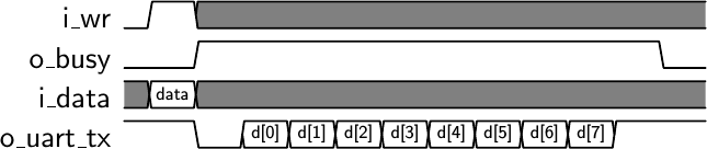 |
The basic “contract” associated with a serial port is that upon any request to send a character, provided you aren’t already busy, that you then send that character as shown in Fig 2 on the right.
This is fairly easy to express in SVA:
	assert property (
		@(posedge i_clk)
		(i_wr)&&(!o_busy)
		|=> ((o_busy) throughout SEND(CLOCKS_PER_BAUD,fsv_data))
		##1 (!o_busy)&&(o_uart_tx)&&(zero_baud_counter));
If you aren’t familiar with this notation, this says that …
-
Following any clock where the module is given a write request, and where the module isn’t busy (
i_wr && !o_busy) … -
The port starts transmitting on the next clock. That’s the
|=>piece. If the left side of the|=>is true (it doesn’t need to be) then whatever follows must be the case. Finally, throughout the whole duration that the port is transmitting,o_busymust be true.This transmitting idea is captured by another sequence
SEND. We’ll get to that next in a moment. For now, notice that we are passing two parameters to it. The first of these is the (fixed) number of clocks per baud, and the second is the data we wish to send. -
Once the port has finished transmitting a character, the
o_busyline should be dropped, and the output wire should be high again.
What about the fsv_data value? Well, it turns out that you can parameterize
SVA
sequences,
and so tailor them to their environment. The values given
to them, though, are not necessarily constant. If the design adjusts any
of the values, the properties within the
sequence
adjust as well.
This was not what I wanted. I wanted to keep track of the byte value that
was requested. Once i_wr && !o_busy is true, however, i_data can be
changed as early as the next clock cycle. Therefore, on a write request,
I captured the data for reference within my design later.
	always @(posedge i_clk)
	if ((i_wr)&&(!o_busy))
fsv_data <= i_data; |
Good! This makes sense so far, so let’s peel the onion back one step further
and dig into the SEND
sequence.
Any
serial port
transmission consists of a start bit, 8-data bits (in this case)
followed by a stop bit, as shown above in Fig. 2 above. Each of these “bits”
fills a baud interval entirely.
Therefore, if we could represent a single
baud interval with a
sequence
of its own, such as one I shall call BAUD_INTERVAL, we can now represent
these ten intervals with a single parameterized
sequence
BAUD_INTERVAL.
	sequence	SEND(CKS, DATA);
		BAUD_INTERVAL(CKS, 1'b0, DATA, 4'h0)
		##1 BAUD_INTERVAL(CKS, DATA[0], {{(1){1'b1}},DATA[7:1]}, 4'h1)
		##1 BAUD_INTERVAL(CKS, DATA[1], {{(2){1'b1}},DATA[7:2]}, 4'h2)
		##1 BAUD_INTERVAL(CKS, DATA[2], {{(3){1'b1}},DATA[7:3]}, 4'h3)
		##1 BAUD_INTERVAL(CKS, DATA[3], {{(4){1'b1}},DATA[7:4]}, 4'h4)
		##1 BAUD_INTERVAL(CKS, DATA[4], {{(5){1'b1}},DATA[7:5]}, 4'h5)
		##1 BAUD_INTERVAL(CKS, DATA[5], {{(6){1'b1}},DATA[7:6]}, 4'h6)
		##1 BAUD_INTERVAL(CKS, DATA[6], {{(7){1'b1}},DATA[7:7]}, 4'h7)
		##1 BAUD_INTERVAL(CKS, DATA[7], 8'hff, 4'h8)
		##1 BAUD_INTERVAL(CKS, 1'b1, 8'hff, 4'h9);
	endsequence
If you’ve never read something like this before, the big thing that you need to
know is that ##1 means “on the next clock”. Hence this
sequence
reads that after the first BAUD_INTERVAL(), another one will start
immediately on the next clock, followed by another, and so on.
The BAUD_INTERVAL()s themselves are parameterized, much like the SEND()
sequence. First, they are parameterized by the number of clocks per baud,
CKS. Then by the value that the output bit is supposed to have, DAT. This
works its way from bit zero all the way to bit 7. They are then parameterized
by the value that the shift register is to have, SR, and finally the value
that the state variable is to have, ST.
Putting all of these together, we can define a BAUD_INTERVAL sequence.
	sequence	BAUD_INTERVAL(CKS, DAT, SR, ST);
		((o_uart_tx == DAT)&&(state == ST)
			&&(lcl_data == SR)
			&&(!zero_baud_counter))[*(CKS-1)]
		##1 (o_uart_tx == DAT)&&(state == ST)
			&&(lcl_data == SR)
			&&(zero_baud_counter);
	endsequence
This
sequence
comes in two parts. The first part lasts CKS-1 clock intervals.
That’s what the [*(CKS-1)] means at the end of the first expression.
The second part follows the ##1, and so comes on the next clock after the
first one. This one is identical, save that zero_baud_counter is now true
indicating the end of the baud interval. Put together, this one
sequence
will require CKS clocks to complete.
You might also notice a subtle bug in this sequence property, having to deal with the number of clocks in the stop bit. I’ve left it in there in order to keep the logic minimal, but the sharp eye might catch it.
Don’t see it? We’ll come back to it in the next section.
Now, remember the difficulties with using
induction?
Because of those, I have constrained all of my state variables in this
one interval. Well, all except the baud_counter. As long as the
formal verification
search depth lasts longer than one baud interval, that shouldn’t be a problem.
At this point in my story, I was rather excited! So far, this was easy. I could formally verify my transmitter using sequences, each sequence used an appropriate abstraction, and so this was quite readable. Yes, if you look through my code, you’ll find many more assertions within it–probably even more than it requires.
It was only when I returned on to my original, full-featured serial port design that I started having problems with these wonderful SystemVerilog sequences.
Verifying the Full-Featured Transmitter
My first approach to verifying the full-featured
transmitter
was to adjust how the BAUD_INTERVAL
sequence
was defined, and then to make
sequences
using my new and improved BAUD_INTERVAL
sequence
for each of the 5, 6, 7, and 8-bit bytes. Things then got interesting as
I tried to implement each of the different types of
parity,
but we’ll ignore that for now. I’m not sure I ever figured out how to do that
using
sequence
properties. However, I had bigger problems before I got to the
parity bits.
It’s not that my design passed or failed, nor was it that I had an example
of a broken trace. The problem I was suffering from was much worse.
But let me slow down, and tell you how I ended up struggling with these wonderful sequence properties.
It started out simply enough: the full featured
transmitter
allows you to adjust the
baud rate.
That should be straightforward. The problem was first that there was no way
to specify a variable number of repeats of a step in a
sequence.
The number of repeats, specified by [*(CKS-1)] above, only worked because
CKS was a parameter and thus fixed at synthesis time. The full featured
serial port
transmitter,
on the other hand, needed to be able to support a variable number of
clock cycles in each baud interval
or it wouldn’t be able to support changing baud
rates.
Therefore, I adjusted the baud
interval sequence to have an undetermined number of clock cycles, and figured
I’d use other properties to force this to work based upon the constraints
found in zero_baud_counter. Once zero_baud_counter became true,
i.e. once the baud
counter reached zero, the solver would exit the sequence.
	sequence	BAUD_INTERVAL(CKS, DAT, SR, ST);
		((o_uart_tx == DAT)&&(state == ST)
			&&(lcl_data == SR)
			&&(!zero_baud_counter))[*0:$]
		##1 (o_uart_tx == DAT)&&(state == ST)
			&&(lcl_data == SR)
			&&(zero_baud_counter);
endsequence |
I then created various SEND5, SEND6, SEND7, and SEND8
sequences,
all composed of a variety of BAUD_INTERVALs within them:
7 baud
intervals in order to send 5-bit data, 8 for sending 6-bits data, etc.
At this point, I was feeling good about this design. Yes, there were more sequences within it than in the lite design. Yes, the sequences were more verbose. Still, I was excited: I was finally getting the hang of SV sequences and starting to really enjoy using them!
That’s when yosys failed to elaborate my design.
As it turns out, I had by now created so many states that yosys was suffering from a complete combinatorial explosion of states my sequence could be in. Once yosys hit 2^16 possible states, it gave up with an error message.
This took me by surprise. There were only 20 states I counted in an 8-bit byte, 18 states in a 7-bit byte, and so forth. How did yosys get to over 2^16 states?
I asked the SymbioticEDA team for some help, and they created a special option which I could use to raise the limit. Perhaps this might fit in 2^17 states?
Nope.
2^18 states?
Not even.
I went as high as somewhere between 2^22 and 2^24 states. I don’t remember the exact number anymore. No matter what number it was, yosys plus my computer clearly couldn’t handle it. This left me unsure of how many states would’ve been required to represent this updated design, since I was never able to expand them all.
The problem stems from the fact that SystemVerilog requires that
sequences
be re-entrant. That is, you can start a
sequence
at any time–even if you are already in the middle of one. In other
words, even though my design would only ever start on i_wr && !o_busy,
and even though o_busy would be true for the rest of the
sequence,
the underlying logic was still trying to account for all of the possibilities
where multiple
sequence
states might be active at a given time.
Ouch. This meant that nothing was working. How was I ever going to verify this design?
Poor Man’s Sequences
Eventually I figured out a solution to the sequence problem. My solution is something I’m going to call a “Poor man’s sequences.” These sequences are built out of immediate assertions, and they don’t use any of the SystemVerilog concurrent assertions that the free version of yosys doesn’t support.
Need to implement an A|=>B sequence? This sequence says that if A is
ever true, then B must be true on the next clock. You may have noticed
that I have been writing,
	always @(posedge i_clk)
	if ((f_past_valid)&&($past(A))
		assert(B);
to describe this case.
Using concurrent assertions, you might’ve written
	assert property (@(posedge i_clk)
		A |=> B);
Using these “Poor man’s sequences”, you might also write,
	reg	f_check;
	initial	f_check = 1'b0;
	always @(posedge i_clk)
		f_check <= A;

	always @(*)
	if (f_check)
		assert(B);
See the idea? Sure, it’s a bit longer and more verbose, but it captures the
idea of A must be followed by B. Indeed, this was how
yosys
was implementing my original logic anyway.
What about a longer sequence? Suppose I wanted a sequence of ten states, such as I might use when transmitting an 8-bit byte over the serial port. How might that work?
	reg	[9:0]	f_sendbyte;
	initial	f_sendbyte = 0;
	always @(posedge i_clk)
	if (i_wr && !o_busy)
		f_sendbyte <= 1;
	else if (zero_baud_counter)
		f_sendbyte <= { f_sendbyte[8:0], 1'b0 };
I can now make a set of assertions based upon what bit is a one within
f_sendbyte.
	always @(posedge i_clk)
	begin
		if (f_sendbyte[0])
			assert(!o_uart_tx);
		if (f_sendbyte[1])
			assert(o_uart_tx == fsv_data[0]);
		if (f_sendbyte[2])
			assert(o_uart_tx == fsv_data[1]);
		if (f_sendbyte[3])
			assert(o_uart_tx == fsv_data[2]);
		if (f_sendbyte[4])
			assert(o_uart_tx == fsv_data[3]);
		if (f_sendbyte[5])
			assert(o_uart_tx == fsv_data[4]);
		if (f_sendbyte[6])
			assert(o_uart_tx == fsv_data[5]);
		if (f_sendbyte[7])
			assert(o_uart_tx == fsv_data[6]);
		if (f_sendbyte[8])
			assert(o_uart_tx == fsv_data[7]);
		if (f_sendbyte[9])
			assert(o_uart_tx);
	end
What else can I do with this? I can assert that only one bit of
f_sendbyte will ever be true at any time.
	always @(*)
	if (f_sendbyte != 0)
		assert($onehot(f_sendbyte));
Okay, $onehot() requires a
yosys
license. On the other hand, if I add to each of my assertions which
unique state the design must be in, and if I do it in such a way that no
two assertions could ever be true at the same time, I can then create
something equivalent.
Alternatively, I suppose I could’ve used a counter to describe each state within this poor man’s sequence. I’m not sure I have a good reason for not using a counter, other than these bit-vector representations still maintained an appearance of supporting the original SystemVerilog sequences–even if they weren’t truly concurrent anymore.
What about the assertions that the design is busy while it is transmitting,
but that it lowers its busy flag once the sequence is complete?
To do this, I need to extend my sendbyte by one more state–the state in
which the busy flag is dropped. This one is a bit unusual. Unlike the
others which all last a full baud
interval, this last state only lasts for one clock cycle at the most.
Hence, I can set and clear it as in:
	reg	[10:0]	f_sendbyte;
	initial	f_sendbyte = 0;
	always @(posedge i_clk)
	if (i_wr && !o_busy)
		f_sendbyte <= 1;
	else if (zero_baud_counter)
		f_sendbyte <= { f_sendbyte[8:0], 1'b0 };
	else if (f_sendbyte[10])
		// Only allow sendbyte[10] to be true for one
		// clock cycle--the cycle where o_busy is false
		f_sendbyte[10] <= 1'b0;
Now I can assert my property that o_busy should be true in the middle of
any character being sent, but false as soon as we are done.
	always @(posedge i_clk)
	if (|f_sendbyte[9:0])
		assert(o_busy);
	else if (f_sendbyte[10])
		assert(!o_busy);
I’ll admit that, while this is mighty expressive, the code that results seems to explode in size. It’s a shame I wasn’t being paid for the number of lines of code I was writing.
There’s also a really subtle bug here that took writing my tutorial to discover: if the last stop bit has the same number of baud clocks as every other baud interval, than the serial port will use one too many clock ticks per byte, as shown in Fig. 5 below.
 |
In order to make sure we can transmit at full speed, we’ll need to make certain
that the next byte can start immediately at the end of the last
baud
interval. This means that on the last clock of the final stop bit, o_busy
must be low indicating that the core is ready to accept a new character
on last clock of the last character. Instead, I had built my design so that
o_busy would stay high throughout the entire duration of the stop bit.
The correct trace should’ve looked like Fig. 6 below.
 |
This is a subtle serial port bug that I wasn’t expecting in my own code. Sure, I’d seen it in the code of others, but in my own?
Oops.
But I digress. Let’s get back to talking about these poor man’s sequences again.
It shouldn’t be too hard to imagine that this bit-vector approach could easily be extended to handle 5, 6, 7 and 8 bit bytes. Indeed, if you look within my serial port code, you’ll find definitions for several sequences:
	reg	[5:0]	f_five_seq;
	reg	[6:0]	f_six_seq;
	reg	[7:0]	f_seven_seq;
	reg	[8:0]	f_eight_seq;
I can also do one critical thing that the SV sequence, approach could not do: I can assert that if any sequence is active, then no other sequences are active.
	always @(*)
	if (f_five_seq)
	begin
		assert(1'b0 == |f_six_seq);
		assert(1'b0 == |f_seven_seq);
		assert(1'b0 == |f_eight_seq);
	end
This plus the $onehot() solution above fixes the explosion of states problem
yosys was struggling with.
But what about the parity bit or the optional second stop bit?
 |
Using SVA sequence, I had been struggling to figure out how to handle the optional parity bit or the optional extra stop bit. Ideally, I’d want to define a single sequence that would follow any byte of data no matter how long, and that would include all of my parity and stop bit options.
This isn’t a problem with these poor man’s sequences, although all of the options I needed to implement made it somewhat of a challenge.
To handle all of these stop sequences, I created yet another bit vector. If
ever we were at the end of a baud
interval (i.e. if ever zero_baud_counter were true), I could check the ends
of my various bit sequences to know if I should enter this new one.
So, for the stop sequence, I created a three bit vector. The first bit would be true during the parity bit–if there was one. The second bit would be true during the first of two stop bits, and the third bit would be true for the final stop bit. This sequence of states then looked something like,
	initial	f_stop_seq = 1'b0;
	always @(posedge i_clk)
	if ((i_reset)||(i_break))
		// This would be equivalent to
		//	disable_iff (i_reset || i_break)
		f_stop_seq <= 0;
	else if (zero_baud_counter)
	begin
		// We'll rebuild every bit of this sequence each time through
		f_stop_seq <= 0;

		// If we are coming from the parity bit ...
		if (f_stop_seq[0])
		begin
			if (dblstop)
				// If there's two stop bits, go to bit '1'
				f_stop_seq[1] <= 1'b1;
			else
				// otherwise go to the last stop bit
				f_stop_seq[2] <= 1'b1;
		end

		// Any time we come from the first of two stop bits,
		// immediately go to the second.
		if (f_stop_seq[1])
			f_stop_seq[2] <= 1'b1;

		// Now let's check for whether we need to enter the
		// stop bit sequence.  Following the last bit of any
		// of our 5, 6, 7, or 8-bit sequences, we'll enter this
		// sequence of final bits.  This therefore merges these
		// sequences with a single stop sequence.
		if (f_eight_seq[8] | f_seven_seq[7] | f_six_seq[6]
			| f_five_seq[5])
		begin
			if (use_parity)
				// If we are using parity,
				//   go to the parity state
				f_stop_seq[0] <= 1'b1;
			else if (dblstop)
				// If we are using two stop bits, go to
				// the first of the two
				f_stop_seq[1] <= 1'b1;
			else
				// In all other cases, go to the one
				// (and only) stop bit period
				f_stop_seq[2] <= 1'b1;
		end
	end
Asserting the properties of each of the various states is now a little bit tedious, but it also works–something which it didn’t before.
As a result, I can now say that I have managed to fully verify both my stripped down serial port transmitter core, as well as the full featured serial port transmitter. Yes, you heard me right, I verified that the core could handle any division of the clock greater than two, 5, 6, 7 or 8 data bits, no parity, a fixed mark or space parity bit, odd or even parity, and one or two stop bits–and all combinations of those options! The core can also handle changing baud rates, something the lite core could not.
Conclusion
I’ve now started using this approach on several of my newer designs. For example, did you notice that at the bottom of my AXI-lite demonstration code I used a sequence like this to create a cover trace? Or, if you’ve been watching my Quad-SPI flash development, you’ll notice I’ve used these poor man’s sequences for reading from the flash, continued reading from the flash, or reading and writing arbitrary bytes to the QSPI interface.
Yes, I think I still like SystemVerilog’s sequence language better. It’s very expressive. However, there’s just some things I haven’t figured out how to express within it that this (uglier) approach using immediate assertions can handle.
Happy is the man that findeth wisdom, and the man that getteth understanding. (Prov 3:13)