Digital PLL Performance (teaser)
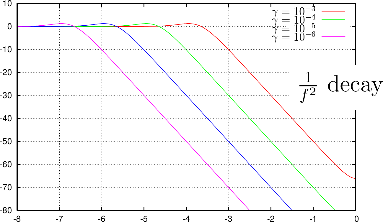
Years ago, I was taught a basic digital and discrete phase lock loop (PLL) implementation. It was a basic type-two PLL that was very easy to implement. You can see its performance below.

I’ve since applied this PLL to many basic tracking problems with a lot of success. One of the features that makes this PLL special, is that it can be implemented without any multiplies. Indeed, this was the basic PLL structure behind the logic PLL I presented earlier.
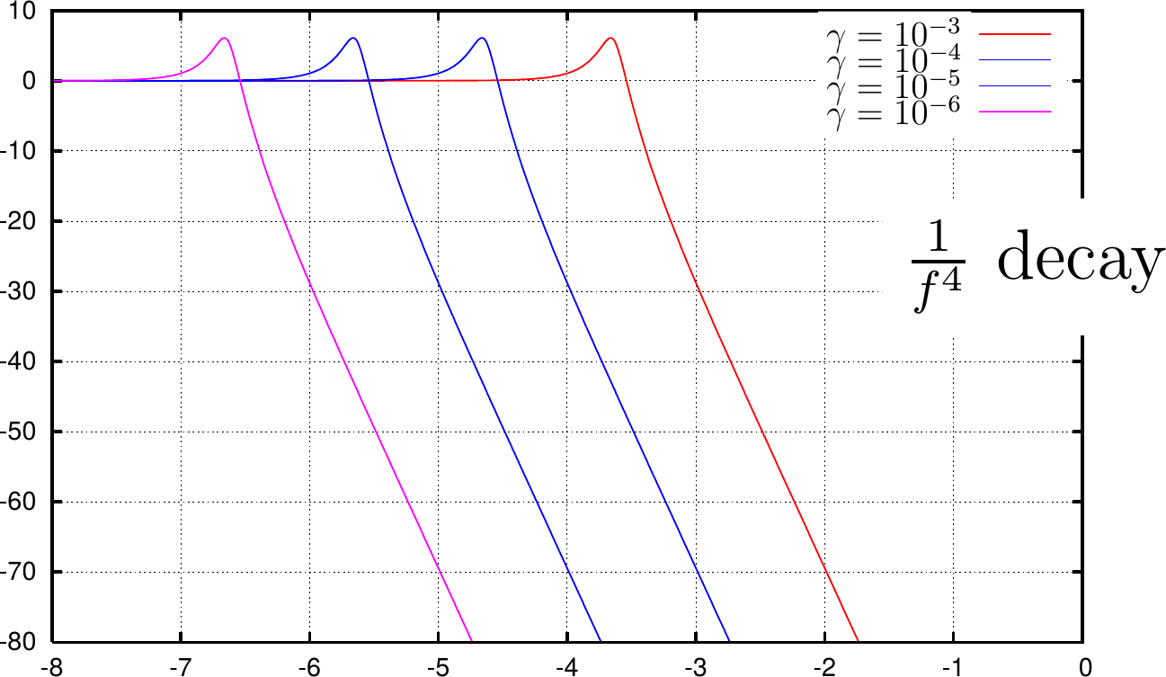
Years later, when I decided that I wanted to try building my own digital PLL structure, I added a recursive averaging filter internal to the loop of that PLL. The result lost some of the nice properties of the simple PLL above, but gained a much sharper out of band cutoff.

To date, I’ve only implemented these PLL’s fully in software. If I get the chance, I’d love to implement them in Verilog. Two realities hold me back: timing and gain.
-
Because these PLL’s are of a more traditional implementation, they require a phase detector (either a multiply or an arctangent) and a sine generator and more. If you count clocks, that’s a clock (or six) to calculate your sine wave, another to multiply the sinewave by the incoming waveform (phase detection), another for the filter, another clock for the two multiplies, another for the accumulator, and so on. Building these PLL’s properly, therefore, will require several tradeoffs.
-
These particular PLL’s are susceptible to changes in the incoming amplitude. While I know of a couple ways to deal with this, I have yet to choose a “right” way.
Perhaps that’s why I haven’t started to present them (yet). Still, it’s on my list of “to-do” items.
If you are interested in learning more about PLL’s and their design, I recommend Gardner’s book, “Phaselock Techniques.”
