
Testing the fast, generic FIR filter
It’s been some time now since we introduced the implementation of a pair of generic filters. The first was a fairly generic FIR filter implementation, and the second was a “cheaper” implementation of the same logic. Both filters filters were presented as though they worked, but without any test bench to prove it. Further, these prior posts hinted at other filters which might be better, but I haven’t come back to present them (yet). (As an example, I’ve got a nice symmetric filter implementation waiting to be present in due time.)
Since that time, we’ve presented a test harness that can be used to prove whether a generic FIR filter even works. We’ve also presented a component of that harness which measures the frequency response of any given FIR filter. Both of these were designed to demonstrate how easy it could be to determine if an HDL filter “works” when using Verilator as our simulator.
Today, let’s take a quick look at our generic filter and see if this test harness can make it testing any easier. We’ll apply four basic tests:
-
Given all coefficients of zero save one, is the impulse response appropriate?
-
Given all maximally valued coefficients and maximally valued inputs, will the filter under test overflow?
-
Given a set of identical and maximal coefficients, does the frequency response cutoff where we expect?
-
Given a more practical set of coefficients, does the filter’s frequency response function look like it should?
These will be the question’s we’ll try to answer in the next section.
Testing the Generic filter
We’ll start by working through the test bench for this filter. We’ve already presented most of the difficult logic (here too), so all that remains now is to create a series of tests and apply them to the filter through our generic test harness.
The first step, though, is to define the constant parameters that the filter was verilated with. We’ve touched on the fact, over time, that I haven’t found a good way to get module parameters into our test bench. Instead, we’ll declare them up top and require the user to remember to keep them in synch with the verilog filter’s synthesized parameters.
const	unsigned	NTAPS = 128;
const	unsigned	IW = 12;
const	unsigned	TW = IW;
const	unsigned	OW = IW+TW+7;
const	unsigned	DELAY= NTAPS; // bits
These parameters are: the number of taps in implemented within the
filter,
NTAPS, the number of bits in an inputs sample, IW, the number of bits in
each filter coefficient,
TW, and the number of output bits. The last parameter, DELAY, is the number
of clocks that need to take place from the time an input is presented to
the filter
until the first response due to the
filter’s
impulse response.
The next step is to set up the Verilator based test bench, and create a filter subclassed from the generic filter test harness.
GENERICFIR_TB	*tb;

int	main(int argc, char **argv) {
	Verilated::commandArgs(argc, argv);
	tb = new GENERICFIR_TB();
We’ll want to test below whether or not the filter’s impulse response is as we think it should be. To do this, we’ll pick values that are the absolute maximum values. We’ll also attempt to turn this filter into a moving averaging filter later to see if we can overflow it. Both of these require maximum constant values.
	const int	TAPVALUE = -(1<<(TW-1));
	const long	IMPULSE  =  (1<<(IW-1))-1;
As a last step before beginning, we’ll allocate some memory for test vectors, and for filter coefficients we might wish to apply as part of a test. We’ll also (optionally) open a VCD file to record the internals of anything that happens. As a final step before beginning, we’ll issue a reset to the unit under test.
	long	tapvec[NTAPS];
	long	ivec[2*NTAPS];

	// tb->trace("trace.vcd");
	tb->reset();
Now for our first test set: let’s walk through all coefficients, setting a
single coefficient to TAPVALUE at a time, and let’s see if we get the
impulse response
we are expecting.
	for(unsigned k=0; k<NTAPS; k++) {
		//
		// Create a new coefficient vector
		//
		// Initialize it with all zeros
		for(unsigned i=0; i<NTAPS; i++)
			tapvec[i] = 0;
		// Then set one value to non-zero
		tapvec[k] = TAPVALUE;

		// Test whether or not this coefficient vector
		// loads properly into the filter
		tb->testload(NTAPS, tapvec);

		// Then test whether or not the filter overflows
		tb->test_overflow();
	}
You may remember from
when we built our
test harness,
that the testload function not only loads coefficients into the
filter,
but it also applies sufficient test vectors to
the filter
to know whether or not the coefficients were validly loaded as desired. In a
similar fashion, the test_overflow() method runs maximum (negative) values
into the
filter
to see if it can be caused to overflow. Both routines will end in an assert()
if something fails.
For our second test, let’s set all of the coefficients to a maximum value. This will create a block average filter.
	for(unsigned i=0; i<NTAPS; i++)
		tapvec[i] = TAPVALUE;
We can then set our filter’s coefficients to be these values, and double check that what we loaded was what we wanted.
tb->testload(NTAPS, tapvec);One of the neat parts of using a block filter is that the filter’s response is easy to predict. Let’s apply a rectangle function to the input of this filter and verify that we get the response we are expecting.
	// Set every element of an array to the same value
	for(unsigned i=0; i<2*NTAPS; i++)
		ivec[i] = IMPULSE;

	// Now apply this vector to the filter
	tb->test(2*NTAPS, ivec);

	// And check that it has the right response
	for(unsigned i=0; i<NTAPS; i++)
		assert(ivec[i] == (i+1)*IMPULSE*TAPVALUE);
These filter coefficients are also the most likely coefficients to overflow–since they are all maximum valued integers for their bit-widths. Let’s see if we can cause this filter to overflow by using these same maximal coefficients as inputs.
assert(tb->test_overflow());As you may recall, the overflow test places inputs into the filter with maximum integer values. It returns true if the filter passes, or false otherwise. (Actually, it fails on an assert error if the filter doesn’t pass here.)
A block average filter should act like a lowpass filter. Let’s evaluate its frequency response, and see whether it matches what we might expect.
	{
		double fp,      // Passband frequency cutoff
			fs,     // Stopband frequency cutoff,
			depth,  // Depth of the stopband
			ripple; // Maximum deviation within the passband

		tb->measure_lowpass(fp, fs, depth, ripple);
		printf("FP     = %f\n", fp);
		printf("FS     = %f\n", fs);
		printf("DEPTH  = %6.2f dB\n", depth);
		printf("RIPPLE = %.2g\n", ripple);

		// The depth of the filter should be between -14 and -13.
		// assert() that here.
		assert(depth < -13);
		assert(depth > -14);
	}
A quick check of the results, shows us that we are in the range we are expecting.
FP     = 0.002441
FS     = 0.006592
DEPTH  = -13.26 dB
RIPPLE = 0.34
In particular, a 13 dB
stopband
is about as much as we might expect from any
moving average filter.
For a final test, let’s load our filter with a set of pre-calculated coefficients so as to implement a half-band lowpass filter. The first step is to load these coefficients into an array.
	for(int i=0; i<NCOEFFS; i++)
		tapvec[i] = icoeffs[i];

	// In case the filter is longer than the number of taps we have,
	// we'll load zero any taps beyond the filters length.
	for(int i=NCOEFFS; i<(int)NTAPS; i++)
		tapvec[i] = 0;
This array can then be loaded into the filter. Once done, we can then test and verify that the coefficients were loaded properly.
tb->testload(NTAPS, tapvec);Now that the filter has a more practical set of coefficients loaded into it, how well did we do? Let’s measure the filter’s frequency response, and report some statistics from it.
	// And let's check that it works by measuring its frequency response
	{
		double fp,      // Passband frequency cutoff
			fs,     // Stopband frequency cutoff,
			depth,  // Depth of the stopband
			ripple; // Maximum deviation within the passband

		tb->measure_lowpass(fp, fs, depth, ripple);
		printf("FP     = %f\n", fp);
		printf("FS     = %f\n", fs);
		printf("DEPTH  = %6.2f dB\n", depth);
		printf("RIPPLE = %.2g\n", ripple);

		// The depth of this stopband should be between -55 and -54 dB
		assert(depth < -54);
		assert(depth > -55);
	}
	printf("SUCCESS\n");

	exit(0);
}
This will lead to the output,
FP     = 0.232910
FS     = 0.267090
DEPTH  = -54.14 dB
RIPPLE = 0.0064
among other outputs.
This looks much better than our prior set of coefficients, and indeed it is.
We now have about a 54 dB
stopband
depth. Further, our
passband
and
stopband frequencies
are both centered around 1/4, just as you would expect for any
half-band
digital filter.
Even better, the distance from the middle of the band to the
passband
cutoff frequency,0.25-0.232910,
is exactly the same as the distance from the middle of the band to the
stopband
start, or 0.267090-0.25.
You can see the frequency response measured by this routine in the charts within our last post on measuring the frequency response of a filter, or below in Fig 1 showing the frequency response in linear units,
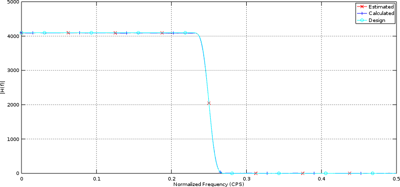 |
while Fig 2 below shows the response of this filter in Decibels.
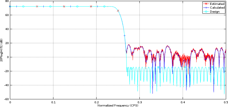 |
In both examples, the calculated frequency response and our test harness estimated frequency response lie on top of each other–giving us reason to believe that our filter performs as desired.
Time for more filters!
Now that we’ve finished discussing how to test/verify a digital filter, it’s time to build some more! Let’s see … I’ve wanted to demonstrate a symmetric filter that’s been waiting on this post, the Hilbert transform should be trivial following the symmetric filter, I’ve got a few slower filters (fewer multiplies) that I can demo … indeed, this might only be the beginning.
On the other hand, there are other CPU based topics that I’ve been ignoring, so it might still take us some time to get to all of these new digital filter implementations.
When your fathers tempted me, proved me, and saw my work. (Ps 95:9)