
Understanding AutoFPGA's address assignment algorithm
Some time ago, I figured out a basic address assignment algorithm for use in AutoFPGA. At the encouragement of my twitter followers, I thought it might be valuable to share this algorithm here.
AutoFPGA, as you may recall, connects peripherals (and now multiple masters in the dev branch) to any respective buses you might wish to assign them to. While AutoFPGA is primarily a copy-paste design facility with some calculation mixed in, address assignment is one of several exceptions to this rule.
Consider as an example the bus structure shown in Fig. 1.
 |
In this structure, you can see three bus masters, together with four basic
slaves, four DOUBLE-type slaves, and four SINGLE-type slaves. Slave one
in particular provides access to a second bus having two slaves on it.
To assign addresses to all of these peripherals, AutoFPGA generates and maintains a list of buses found within the design. Each bus is composed of a number of peripherals (the PLIST), and one or more masters (the MLIST). Certain special “subbus” or “arbiter” masters are able to cross from one bus to another, making it possible to have hierarchical bus structures, such as Fig. 1 shows above.
 |
AutoFPGAs
first task is to split each bus into three
parts: The first is for
peripherals of type SINGLE. These are single register peripherals whose
register is immediately available for reading or writing, and who don’t stall
the bus. The second set of peripherals, those of type DOUBLE, can have
more registers internal to them. This set requires a single clock period to
return a value from a bus request. As with the SINGLE list, this set is
not allowed to stall the bus either. The last set of peripherals contains all
other types of peripherals.
For WB peripherals,
the entire SINGLE peripheral set is turned into a DOUBLE peripheral, and
then that peripheral is turned into a regular peripheral of the normal variety.
While this is captured in Figs. 1 and 2 above, I haven’t yet decided if I will
do the same thing for the
AXI-lite interface or not.
Address assignment then starts at the lowest level of the bus structure, and
then works its way up to the top. Within any given level, the SINGLE set is
assigned first and formed into its own peripheral, then the DOUBLE set,
and then peripheral assignment is done on the rest of the bus.
Let’s look at an example from one of my more recent projects.
 |
In this project there’s your basic ZipCPU, and then flash, SDRAM, network, and SD-Card peripherals. Indeed, this much of the design is based upon my VideoZip design. Now, using AutoFPGA, I can add a basic SONAR transmit controller and a boot ROM section so my customer doesn’t need to load code into the design himself. (The boot ROM slave isn’t shown in Fig. 3 above.) Finally, there’s a data recorder shown above as the “DMA” in the picture. If you look carefully, you’ll notice this same slave exists on the bus in two places: once where for the control port where it receives its commands, and again for the memory access portion where it masters the bus. Xilinx users might be familiar with the similar AXIS2MM data mover peripheral, but this particular one is my own WB creation and no real relation to theirs.
Let’s spend a moment to see how AutoFPGA handles this address assignment problem.
Address Decoding
The first step to understanding how address assignment works is to understand how addresses are decoded. As we’ve discussed before, address decoding is done with two values: an address and a mask assigned on a per-slave basis. A particular peripheral is selected if the requested address matches the slave’s address everywhere a mask bit is set.
request[peripheral] = valid_request
		&& ((requested_address & SLAVE_MASK) == SLAVE_ADDR);
You might also equivalently write,
request[peripheral] = valid_request
		&& (((requested_address ^ SLAVE_ADDR)&SLAVE_MASK) == 0);
Both should generate the same logic.
In general, the goal of address assignment is to both minimize the number of mask bits and the number of address bits at the same time.
Sound simple? Let’s find out how this works.
Easy Address Assignment
Just to illustrate the issue of address assignment, let’s start out with a basic set of peripherals and assign an address to each of them. I’ve chosen a set of 12-peripherals for this purpose, shown in Fig. 4 on the right.
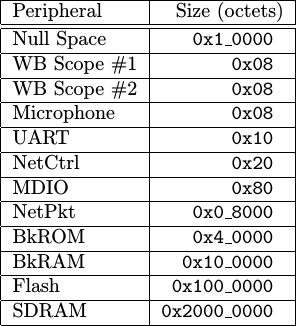 |
-
The first “peripheral” is the null space.
My initial designs didn’t include this null space. Shall we say I got burned and then painfully learned the wisdom of my ways?
The story dates back to before I implemented illegal instruction detection in the ZipCPU, feeling at the time that it was “optional”. (I don’t feel this way any more.) Then one day something went wrong. Somewhere, a pointer got set to address zero. Worse, all of my peripheral addresses were packed near zero at the time. The result was that the CPU started wildly writing errant data to the peripheral address space.
By the time I had realized what was happening, the CPU had written to the flash configuration control register and switched some of the one-time programmable configuration bits. My Arty, while usable, has never been the same since.
I’ve also learned to add illegal instruction detection and bus error bus error detection to the CPU, and similarly a null space to my address assignments.
-
The next couple of peripherals in this example set are Wishbone Scopes. These require only two addresses, 4-bytes each, one for control and one for data.
-
I also have a microphone peripheral with a similar addressing scheme–one address for control and one for data.
-
The next peripheral is my WBUART peripheral. This has transmit and receive registers, as well as protocol control and FIFO status registers. This peripheral therefore requires address space for four 32-bit registers.
-
My RGMII and RMII controllers need two address regions–one for packet memory and another for the controller. The controller itself requires eight 32-bit registers to control the transmitter, the receiver, the MAC address, and to some feedback counters to capture the number of aborted packets.
-
These are followed by the network management data port. My network management controller provides a separate address for everything in the MDIO address space, so it requires 128 bytes of address space.
-
The network packet memory needs to be sufficiently large to hold both a received packet as well as the packet to be transmitted next. Let’s pick a memory area 32,768 bytes wide (two 16kB packets) knowing that we can adjust this for other architectures.
-
While I don’t typically use a first-stage boot-loader, one of the projects I’m working on requires it. That project requires a boot-ROM so we’ll throw it in here. A block-ROM of 256kB is more than sufficient to read a program from an SD-card and copy it to RAM.
-
We’ll then scrap together whatever’s left of our FPGA block RAM components in order to create a 1MB block RAM peripheral.
-
We also have a flash peripheral in this sample list. It seems there’s a large set of flash peripherals stuck at 24-bit addressing, so this will give us a flash size of 16MB.
-
Our final peripheral is a DDR3 SDRAM having 512MB of memory. My current approach to this is to use the basic MIG controller, coupled with a Wishbone to AXI bridge. As you’ll see in a moment, the sheer size of this particular peripheral will dominate much of how our address assignment algorithm will work.
Now, let me ask, how would you assign addresses to these peripherals?
Ideally, what we might want would be a one-hot addressing scheme where you could tell which peripheral was addressed by a single bit in the address space. While this sounds like an awesome idea, it fails in practice any time an errant program accesses an address with more than one of these otherwise one-hot bits set. If both peripherals respond, … “bad” things will happen. The bus, for example, might lock up until the next power cycle. This is usually quite “bad”.
This would also break the fundamental rule of all bus work: for every request, there is one and only one response.
No, we want to make certain instead that our address assignment method works in such a way that only one slave will ever be addressed at a time. It doesn’t matter if “non-allocated” addresses select that slave, but it does matter if any addresses select more than one slave at a time.
Perhaps the easiest way to do address assignment might be to first find
the slave with the biggest address width, and then assign an address space
that big to every slave. Since the
SDRAM
requires an address space of
0x2000_0000 bytes, we’ll assign every peripheral that many bytes and just
count up.
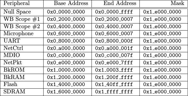 |
As you can see from Fig. 5 on the left, we overran our 32-bit address space and now need a 33-bit address space. You can also see that our 8-byte peripherals were assigned 512 MBs of address space each. This would sort of be like running a parcel shipping business and only supporting one size container–train box cars.
Practically, this will never work.
The ZipCPU
only supports a 32-bit address space (i.e. 30-bit word address space), and
of that address space there’s a reserved portion at the end from
0xff00_0000 to 0xffff_ffff.
Before we abandon this approach though, let’s see what else we might learn
from it. For example, the address decoder could decode all of these separate
peripheral address ranges with a simple 4-bit lookup table, checking only
address bits 33-29 as indicated by the mask, 0x1_e000_0000.
While this is a low-logic decoder, it does have a consequence. Low-logic means that peripherals with a small address range may exist at multiple locations in the address map. To continue our parcel shipping analogy, many loaves of bread might find in a package big enough to hold a sofa–why only pack one peripheral in such a large address space?
Further, consider how the UART
peripheral exists from 0x8000_000f to
0x9fff_ffff even though it only uses four registers within that range.
What happens, then, is that all of the addresses within this range will
alias into the same four peripheral registers, allowing the
UART
to be addressed anywhere in that address region. We’ll touch more on this
in the next section.
For now, we can summarize our success, or lack thereof, by two metrics–the address width required to access all of these peripherals (33 bits–too many), and the number of mask bits necessary to select between them, 4-bits.
Can we do better?
Tightly packing addresses
When I first started trying to handle address assignment, I would pack as many peripherals as I could into a given address area. Here’s how that algorithm worked:
-
I’d first sort all the peripherals, leaving the null space at zero of course.
Perhaps you’ve noticed that I’ve already sorted the peripherals listed in Fig. 4 above.
-
I’d initialize my work by setting a
start_addresseither to 0. -
For each peripheral, starting with the “empty” null-space and working down the list, I’d add to the
start_addressthe size of the peripheral, minus one byte.
	pa = peripheral[k]->address_width();
periphera[k]->base_address = start_address + (1<<pa)-1;-
This would be guaranteed to overflow if there weren’t enough bits to support my requested address range. For example, suppose the start address was
0x40and I wanted to allocate space for the MDIO peripheral–requiring a register space of0x80octets. If you add these two together, you’d get0x40 + 0x80 = 0xc0. Subtracting one brings you to0xbf. -
Now I can trim off the bottom bits, to guarantee the peripheral can use an address mask.
	pa = peripheral[k]->address_width();
periphera[k]->base_address = &= (-1l << pa);-
To follow our example from above, this would force the MDIO peripheral needing
0x80bytes of address space to have a start address equal to0x80–plenty of room, and with a guaranteed 7-bits to reference values within the peripheral. -
We can then increment our start address to be ready for the next peripheral. The new start address must be just following our assigned address space. So, for our
start_address = peripheral[k]->base_address + (1ul<<pa);- Then, as a first pass to knowing what mask bits we require, we set our mask bits to be the next address bit over.
periheral[k]->mask_bits = (-1l)<<pa;- Finally, go back and repeat for all peripherals.
This sounds confusing. Perhaps a picture or two might help.
 |
The two scopes and the microphone all use two words of address space. We can therefore pack them tightly together. However, when we get to the UART, we need an address that’s aligned with four bus words. Rounding up to the nearest address that’s aligned with four bus words is going to require stuffing two words of unused space into our address space as shown in Fig. 6 on the right.
 |
Once we’ve assigned the scopes and the UART, it’s now time to assign an address to the network control port. This peripheral needs an address aligned to eight 32-bit words. However, if you shuffle everything to an eight word width, you’ll find that the network control addresses don’t fit unless you skip some more space.
As you can see, we’re working from the smaller peripheral to the larger ones. At each level, the peripheral needs to be assigned to an address aligned to the size of the peripheral.
That’s what the algorithm above does.
As a last step, we’ll measure the total number of bits required to do this address decoding (30 bits), and then trim any mask bits to just that many bits. The result would be a set of base addresses and masks describing a “full address decoder”.
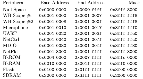 |
This time, you’ll notice from Fig. 8 above that we’ve done much better at minimizing the number of address bits than we did in our first attempt shown in Fig. 5 above. But 27 mask bits? Not so much.
If low logic were important to us, and it has always been to me since more logic costs more money, we might choose to just check the minimum mask bits necessary to separate peripherals. This would be a “partial address decoding”, since it would leave holes in the address space. You can see how this might work in Fig. 9 below.
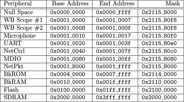 |
If you count number of bits used in the masks of Fig. 9, you’ll get eleven non-zero bits. Eleven mask bits would mean that decoding a peripheral’s address would require a comparator with a length somewhere between one bit (the SDRAM) and 11-bits (the WB Scopes). Decoding addresses using an 11-bit mask would require between two and three LUTs per slave depending on your architecture.
While this kind of “partial address decoding” is both common and cost
effective, it’s been known to surprise those who aren’t familiar with it.
Consider as an example address 0x210_0000. Since the
block RAM’s mask only checks bits 0x2110_0000, our address decoding
algorithm above will map this address to the block RAM–even though the
block RAM’s official address space only exists between 0x10_0000 and
0x1f_ffff. On the other hand, 0x20c_0000 would map to our block ROM,
0x30c_0000 would map to our Flash
peripheral,
and 0x4003_0000 would map to our first WB
Scope).
This isn’t a bug, but it can be a rather surprising consequence
the address decoding algorithm.
So, all in all, we did okay here with our second attempt at address assignment. AutoFPGA, however, has a better approach to generating a “partial address decoding” mask, which we’ll discuss in the next section.
AutoFPGAs Address Assignment Algorithm
What we’ve done above nearly describes AutoFPGA’s address assignment algorithm. There’s only one piece missing: minimizing the required size of the mask.
To handle this, AutoFPGA takes a first pass through the peripheral list to calculate the minimum total address size. It then increases the minimum peripheral address size as long as the total address width remains less than the minimum address width, and as long as the number of mask bits goes down.
How shall the minimum total address size be calculated? Just the way we did it in our last section: add peripherals to a bus and calculate the address width. The number of relevant bits is then given by the difference between the full address size and the bloated minimum size given to every slave.
For example, if we look through our example slave set, you’ll see that the maximum slave size that doesn’t increase increase the address width is 25 bits. Once chosen, each slave is checked for its address size. If the slaves address size is less than 25 bits, it is replaced by 25 bits in the algorithm above. The algorithm then continues as before.
For the slave set example we’ve been working with today, the result then looks like Fig. 10 below.
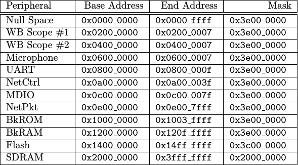 |
You might notice that the base address just increments from one peripheral to the next–that’s the minimum address size amount. Further, the peripheral’s are just one step away from each other up until the last peripheral–the SDRAM again.
Looking at Fig. 10 again, you’ll notice that the total address width is just one more than the SDRAM’s address width. This is the minimum possible address width we could’ve achieved. Similarly, you’ll also notice that the address calculation now fits in a 5-bit mask. Since Xilinx chips allow packing two 5-LUTs into a single 6-LUT as long as the wires are the same, that means we can do our address decoding with only six pairs of 5-LUTs.
Bus Hierarchies
This same basic approach maps quite nicely to bus hierarchies as well, where one bus master is a slave to another bus above it. AutoFPGA handles bus hierarchies by simply walking the bus tree from the bottom on up.
-
Start at the lowest bus in the hierarchy. Assign addresses to it. Once accomplished, you’ll then know the address width of this sub-bus within the hierarchy.
This width is used to fill key tags within an bus-translator or arbiter components, allowing them to be adjusted for the width of the bus they are working with.
-
Once you then move up in the hierarchy, you can treat each bus beneath as a self-contained slave.
Where this starts to get interesting is if you have multiple tops to the bus tree, and those tops each have a different perspective of the address map. I’ve already had this problem once with both the ZipCPU and the debugging bus occupying the top of the tree. My solution was rather hackish to force a specific arrangment of the two buses, but I’m likely going to need to revisit it in the future.
Since I’m only just now starting to handle multipl-masters with AutoFPGA, rather than using an arbiter to neck down every bus to a single master, I’m not quite sure how this is going to impact things … yet.
Conclusions
I’m sure there are more complicated address assignment algorithms out there, but this one has worked rather nicely for me for some time.
It’s not perfect. One of the particular limitations of this algorithm as written is that it doesn’t (yet) handle the case where some peripherals have pre-assigned addresses and others need to be assigned around those. This means that every time your run AutoFPGA the address structure might change. That’s not necessarily a good thing when you’ve already delivered a product to your client and you just want to add a new piece of hardware to the address decoder without obsoleting all of the software you’ve already written. In other words, allowing the address space to be fixed is something I am very interested in addressing in the future.
On the other hand, if you have control over all of the parts of a project and have no problems rebuilding all of your software on every reconfiguration, then AutoFPGA might be the solution you need. Not only does it move things around, but it then updates a series of header and data files that you can then use to keep running the same software once recompiled. As a result, if I simply run
$ make autodata
$ make
all of the addresses may get reassigned, but all of the software will rebuilt
at the same time to support the new address space. On the other hand,
address reassignment isn’t automatic–if I don’t run make autodata then
the design should work as is with the current address assignments.
What do you think? Feel free to drop me a line or re-post this article if you felt this material was valuable.
But he said unto them, Give ye them to eat. And they said, We have no more but five loaves and two fishes; except we should go and buy meat for all this people. For they were about five thousand men. And he said to his disciples, Make them sit down by fifties in a company. (Luke 9:13-14)