
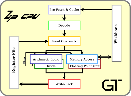
A Quick Introduction to the ZipCPU Instruction Set
 |
If you aren’t familiar with the ZipCPU, then you should know that it is my attempt at improving the publicly available softcore CPU architectures. It has been designed from the ground up to be a truly Reduced instruction set computer, or RISC machine, to have a simple pipeline implementation, and yet to be able to run a multi-tasking operating system if desired. Unlike many of the other more common soft-core CPUs, such as MicroBlaze or the NiosII, the ZipCPU has been created in a completely open source fashion.
The ZipCPU was also designed to run on the cheaper, more commodity, FPGA hardware platforms. Indeed, in many ways this has always been the philosophy behind the ZipCPU: be small and simple, yet fully and completely functional. I judged, as I built it this way, that not only would it be easier to build and debug a simpler CPU, but also that it would be easier to add to an FPGA project as an afterthought if it was small.
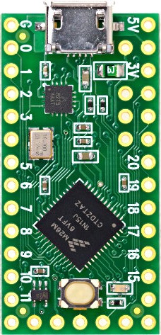 |
Consider, for a moment: if you bought an FPGA, you did so for a purpose. If you wanted a CPU instead then there are many other CPU’s that you could have bought that would have run faster, and cost less, than the FPGA you purchased. As an example, Fig 2 shows a picture of the TeensyLC–a small CPU that sells for only $15USD. Since you didn’t purchase a TeensyLC, you must have purchased that FPGA for a reason–to perform a task that you couldn’t do with an off-the-shelf CPU. Indeed, I would imagine you want as much of your FPGA available to complete that task as possible. If, in the process, you find yourself needing a CPU on the same chip as your FPGA–then you want that CPU to stay out of the way, and to consume as few resources as possible.
This is, and was, the purpose of the ZipCPU.
We’ve already discussed several of the parts and pieces of the ZipCPU across many articles over the last year. For example, we discussed the divide unit when we discussed minimizing FPGA resource allocation. We discussed the ALU unit when describing how a simple ALU might be structured. We discussed the debugging needs of a CPU in general, as well as how to meet those needs in both simulation and in the hardware. More recently, we presented and formally verified a simple prefetch engine for the wishbone bus. Indeed, my recent post about the ugliest bug I’ve ever encountered was also based upon my experiences with the ZipCPU.
Today, let’s take a look at how the ZipCPU instruction set is laid out, and discuss a few of the ways it is different from some of the other, more common, soft-core CPUs of today. Our intention will by no means be to present a complete description of the ISA, but rather an overview. The ZipCPU specificationshould provide any missing details–if not, please let me know if you find something missing and I can add it in.
The Basic Operations
The ZipCPU was designed around a set of instructions all having the very simple form,
OP.X #+Rb,Ra |
You can read this generic instruction as: if X is true, then OP is applied
to the number # plus the value of register Rb, and the register Ra,
and the result is placed into Ra. Here I’m using # to refer to an
immediate value–a fixed number encoded within the instruction stream.
Fig 3 attempts to show this operation graphically. Two registers are read
from the register file, noted here as Ra and Rb. An immediate is added
to register Rb, or alternatively the immediate replaces Rb entirely,
and the result joins Ra to be operated upon.
For ALU instructions, the result is only written back if the condition is true.
Memory instructions are just a touch different. In the case of a memory
instruction, the #+Rb value (immediate number plus the value of register
Rb) is used as the address for the memory operation. Further, the
operation only begins if the condition is true. Ra is used as the
data source for a store operation, or the data result of a load operation.
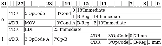 |
The encoding for this and other ZipCPU instructions are shown
in Fig 4 on the right. Four bits are used to encode the destination register,
Ra, five bits are used to encode the opcode, OP, three bits are used to
encode the condition, X, and the remaining bits are used to encode whether
or not Rb is used and what immediate offset is used by the instruction.
Two instructions have special formats: the MOV (move) and LDI (load
immediate) instructions, we’ll come back to these further on.
The ZipCPU can also support compressed instructions, with their format shown at the bottom of Fig 4. While we’ll only touch on the Compressed Instruction Set today, you can read all about these two-for-one instructions in the ZipCPU specification if you are interested.
Indeed, the ZipCPU instruction set architecture is just about that simple. Still, let’s dig into some more details.
The Basic Operations, in more detail
Most RISC CPUs today tend to support a six bit opcode or larger. This allows these machines to support up to 64 basic instructions–or even more. Not the ZipCPU.
The ZipCPU was designed to be a truly Reduced instruction set computer. As a result, it doesn’t have nearly as many instructions as its competitors: the lm32 processor, OpenRISC, RISC-V, NiosII, and MicroBlaze. We can go over some of these differences later.
 instructions)](/img/zipcpu-insns.png) |
For now, let’s take a quick look at the ZipCPU instruction cheat sheet, shown
in Fig 5. From here, you can see that the ZipCPU supports 25 basic
instructions.
It has four special instructions, BREAK, LOCK, NOOP, and SIM,
and another six instructions reserved for a floating point co-processor–these
are the FP instructions. Further, eight instructions have been chosen to
also have a compressed representation.
That’s it. There are no more or hidden instructions, although a lot of the instructions within this list have some special functionality.
Shall we walk through these instructions, and discuss what each does in turn?
-
SUBtract, subtracts
#+Rbfrom the value inRa, leaving the result inRa.I’ll write this as
Ra <= Ra - (#+Rb)to facilitate a simpler notation, since just about all of the instructions will have this form. -
AND,
Ra <= Ra & (#+Rb) -
ADD,
Ra <= Ra + (#+Rb) -
OR,
Ra <= Ra | (#+Rb) -
XOR,
Ra <= Ra ^ (#+Rb) -
LSR,
Ra <= Ra >> (#+Rb)(assumes Ra is unsigned)In all of the ZipCPU’s shift instructions, the last bit shifted out of
Rais placed into the Carry flag.Further, these shift instructions accept requests for shifts outside of the reasonable bounds
0--31, permitting instead any shift amount between0and2^31–not that you’d need these extra amounts. -
LSL,
Ra <= Ra << (#+Rb) -
ASR,
Ra <= Ra >> (#+Rb)This instruction implements an Arithmetic right shift. This is done by first assuming that
Rais signed, and then propagating the sign bit from the MSB down. -
BREV, This is the “bit-reverse” instruction. For this instruction,
Rais assigned the value of(#+Rb)but not until(#+Rb)has been “bit-reversed”. That is, bit 0 of(#+Rb)becomes bit 31 ofRa, bit 1 becomes bit 30, etc.This instruction is very unique to the ZipCPU, and yet it is also very fundamental to how the ZipCPU operates. By using a BREV instruction, the ZipCPU can load any 18-bit value into the upper bits of a register. If it is then followed by a LDILO, the pair of instructions can then load any 32-bit value into a register.
The BREV instruction is also very useful for bit-reversed addressing and bit-manipulation functions–such as counting trailing zeros in a number. It’s also used for the CLR (clear register) derived instruction.
-
LDILO, or Load Immediate Lo, assigns the lower 16 bits of
Rato the lower 16 bits of(#+Rb) -
MPYUHI, or multiply unsigned values and return the upper 32-bits, sets
Rato(Ra*(#+Rb)) >>32. The multiplication involved assumes bothRaand(#+Rb)are unsigned numbers. -
MPYSHI, or multiply signed values and return the upper 32-bits, is identical to
MPYUHI, with the exception that the multiplication is done assuming bothRaand(#+Rb)are signed numbers. -
MPY, a 32x32-bit multiply which returns the lower bits of the result. Basically, this is given by
Ra <= Ra * (#+Rb), with the exception thatRais set to the lower 32-bits of the product. -
DIVU, a 32x32-bit unsigned divide.
Ra <= Ra / (#+Rb) -
DIVS, a 32x32-bit signed divide.
Ra <= Ra / (#+Rb) -
CMP, Compare. Sets the flags according to
Ra - (#+Rb). This instruction is implemented identically to the SUB instruction above, save that only the flags are affected by a CMP instruction.Rais not written back to the register file. -
TEST, is identical to the AND instruction, save that like the CMP instruction, TEST only sets the flags register and leaves
Rauntouched.
Two more basic instructions have subtly different forms.
-
MOV, a move instruction,
Ra <= (#+Rb). In this case, the move instruction always has anRbregister. If you want to move just the constant into a register, then use the LDI instruction instead.The MOV instruction has the additional capability of moving values between register sets–something we’ll need to get to later. As a result, the range of the immediate values supported by the move instruction (13-bits) is not quite as many as those supported by the rest of the instructions above (either 14-bits or 18-bits).
-
LDI, or load immediate, has a little bit of a different form. The LDI instruction has no
Rbregister option. It is used for loading arbitrary values intoRa, and written asRa <= #.This instruction has also been stripped to its bare essentials to be able to load the largest value into a register as possible. As a result, it can load any 23-bit signed value into a register. Anything more requires a combination of a
BREVinstruction and anLDILOinstruction.
The next six instructions are memory instructions. These are written a little differently, but they still read from left to right. For example,
SW.X Ra,#(Rb)stores the value of Ra into the address given by # plus the Rb register,
while
LW.X #(Rb),Raloads the value of Ra based upon the contents of memory given by the address
in Rb plus the offset, #. Both of these can be executed conditionally,
if the condition X is true. (More on that later.)
Both of these instructions operate on a word, hence their mnemonic is store word or load word respectively. The ZipCPU supports four other memory instructions:
- LH or load halfword. This instruction loads a 16-bit value from memory
into
Raand then clears the upper 16-bits to get the result to fit into 32-bits. - SH or store halfword. This instruction stores the bottom 16-bits of a register into memory.
- LB or load byte. The upper 24-bits are cleared.
- SB or store byte
These are all of the basic ZipCPU instructions.
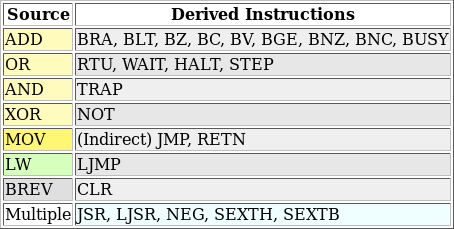 |
See anything missing? If you are familiar with other CPUs, you may notice a lot of missing instructions. None of these, however, are truly required as combinations of the instructions above can be used to implement almost any instruction you might need. For example, Fig 6 shows several examples of instructions the assembler understands, yet whose implementation is derived from the instructions above.
Let’s back up a bit, though, and discuss the registers on the ZipCPU.
The Basic ZipCPU Register Set
 registers: R0 (or LR), R1-R11, R12 (or FP), SP, CC, and PC. There are two sets of these, one prefixed with u for user, the other prefixed with s for supervisor](/img/zipcpu-registers.png) |
The ZipCPU supports sixteen 32-bit registers in two sets, but
we’ll come back to the issue of the different register sets later. For now,
each set of sixteen registers is organized into registers R0-R15. From
the hardware standpoint, all but the last two are general purpose, whereas
the compiler treats all but four of these registers as general purpose
registers.
Of these sixteen registers, the hardware treats the last two as special purpose
registers. R15 is the
program counter,
or PC. This register maintains
the address of the next instruction the ZipCPU will execute within it.
R14 also has a special purpose–it is the condition code and
status register,
or CC. Flags, such as whether or not the result of the last
operation was zero or not, are stored in the bottom four bits of the CC
register.
While the ZipCPU instruction set doesn’t have any branch instructions per se, three of the basic instructions above can be applied to the program counter in order to create branch instructions.
-
LDI #,PCloads a 23’bit signed immediate value into the program counter,PC. It can be used any time the absolute address of the destination is known by the assembler before linking–which isn’t very often. -
ADD #,PCadds an amount to the program counter,PC. This will execute a local branch, causing the CPU to read its next instruction#words earlier or later depending on the sign of#. Since this is such a common instruction, this is often abbreviated with by a branch always instruction,BRA <address label>.The
BRAinstruction is often used for jumping between locations within a given function–such as when executing a loop or an if. It is used anytime the assembler can tell that the distance to the target will fit within 18-bits. -
LW (PC),PCfollowed by a new address, reads a new value of the program counter from the next word in instruction memory. This instruction is used heavily by the linker, since the next address in memory can later be simply set to any value once that value is known. This is also known as a long jump instruction, and so the assembler understands theLJMP <address label>mnemonic, where<address label>is an assembly label of where you wish to jump to.When the ZipCPU is built with the early branching option, for a cost of about 80 LUTs, and the prefetch with instruction cache, this instruction only costs three clock cycles.
The ZipCPU
port
of GCC
treats R0, R14, and (sometimes) R13 as special registers.
R0 is known as the link register, LR, where the return address to a
subroutine is kept. This leads to two other instructions:
-
MOV 8(PC),R0followed byLJMP <function>is how the ZipCPU implements a long jump to subroutine command, LJSR–a shorter jump can be implemented with theBRAinstruction–but only if the destination is known at assembly time to be in range. The assembler handles all of the constants, and selects between the instruction forms for you, so you may find these instruction pairs written in assembly as eitherJSR <function>orLJSR <function>. -
MOV R0,PCloads the link register back into the program counter. This is often the last instruction in any function. Indeed, it is so common that the assembler will also accept the RETN mnemonic for this instruction.
The GCC back
end
uses R14 as the stack
pointer, SP. Hence, you
might see SW R0,(SP) which will store R0 onto the
stack.
If you choose not to optimize your code, and sometimes even if you do,
the compiler will use R13 as a frame pointer, FP. This register is
similar to the stack pointer,
and used to reference local variables within a function. In
general, I’ve tried to keep the compiler from using R13 as a frame
pointer though–since it further limits the 14 general purpose registers.
It’s for these reasons that, at the beginning of any function, you’ll often see code looking like:
function_name:
	SUB 12,SP
	SW  R0,(SP)
	SW  R1,4(SP)
	; etc
This allocates three words on the
stack.
of four bytes each, and then uses the first two of them
to store R0 and R1 respectively–presumably because the compiled routine
is going to clobber those registers and wants to use their values or restore
them later.
You may then find, at the end that function, code that looks like,
	LW  (SP),R0
	LW  4(SP),R1
	ADD 12,SP
	RETN	; Implemented as MOV R0,PC
This code loads the original values of R0 and R1 back from the
stack,
restores the stack pointer,
to its original value, and then finally returns
to the place where it was called from.
Conditions
When I introduced the form of the
ZipCPU instructions above, I mentioned
that almost all instructions had the form OP.X #+Rb,Ra. We’ve examined
the various operations, OP, and the various registers that Ra and Rb
can take on, but we haven’t discussed the conditions, X.
It is the condition X that allows almost every
ZipCPU
instruction to be executed conditionally.
The ZipCPU supports 8 conditions,
or possibly values for the X, as shown in Fig 8.
 supports eight conditions: (none), if zero, if less than, if greater than or equal, if overflow, and negations of these for all but overflow](/img/zipcpu-conditions.png) |
-
If no condition is specified with the instruction, then the ZipCPU will always perform the indicated instruction.
-
Z, or the zero condition, will cause an instruction to only execute if theZflag in the condition codes is set.If you are not familiar with condition codes, the basic idea is that if the result of the last instruction was a
Zero, then theZbit will be set. Hence, if you compare (i.e. subtract) two registers and the result is zero, then you know the registers are equal and you can use theZbit to do logic assuming the registers were equal. -
LT, the less than condition, will cause an instruction to execute only if the result of the last instruction was less than zero. This is a signed comparison result, focusing on theNegative bit in the condition codes. -
C, will cause an instruction to execute only if the carry bit is set.This is also how the compiler implements an unsigned less than condition.
-
V, will cause an instruction to execute only if the oVerflow bit is set. The ZipCPU port of GCC doesn’t yet use this flag, but it may do so in the future.
The last three
flags
are just negations of the earlier
flags.
There’s NZ, or not zero, GE, or greater than or equal to, and there’s
NC to test if the carry bit is not set (i.e., unsigned greater than or
equal to).
The most common use of these conditions is in
branching
operators. For
example, ADD.Z #,PC will cause the
CPU
to jump only if the Zero bit is set. Since this is also a
very common operation, the
assembler
understands seven
branch
instruction implementing ADD.X: BZ
(branch
if zero), BNZ
(branch
if not zero), BLT
(branch
if less than), BGE
(branch
if greater than or equal), BC
(branch
if carry is set), BNC
(branch
if carry is not set), and finally BV
(branch
on overflow).
You can also use these conditions to test multiple things at once. For
example, suppose you wanted to know if registers R0, R1, R2, and
R3 were all zero, and you wish to
branch
to some target if they are all zero. In this case, you might write:
	CMP 0,R0
	CMP.Z 0,R1
	CMP.Z 0,R2
	CMP.Z 0,R3
	BZ all_zero
You could also do a test of whether or not just one of them was zero, such as:
	CMP 0,R0
	CMP.NZ 0,R1
	CMP.NZ 0,R2
	CMP.NZ 0,R3
	BNZ one_of_these_is_nonzero
These work because the CMP and TST instructions always set the
condition codes–even
when executed conditionally. Other instructions,
when executed conditionally, don’t affect the
condition codes–allowing
strings of conditional instructions to all depend upon the same condition.
A good example of multiple instructions depending upon a single condition
would be an integer absolute value calculation.
Suppose you wanted to calculate the absolute value of R0 and leave the
result in R0. You might then write,
	TEST R0
	XOR.LT -1,R0
	ADD.LT 1,R0
The first instruction AND’s R0 with -1–the default value if no other
value is given to TEST. Since this is a TEST instruction, R0 is
left unchanged and only the
flags are affected.
In this case, the N flag will be set if R0 is negative. We can then
complement every bit and add one to R0 to negate it.
Notice how, in this process, the XOR instruction didn’t affect the
flags, making it possible
to string the ADD function to this chain as well–all operating only if
R0 was negative.
Why are conditional instructions a good thing? There is a real method and purpose to this madness. Conditional branches on the ZipCPU cost about 5-clocks, whereas conditionally executed ALU instructions still cost only one clock. Hence, the absolute value calculation above costs 3-clocks (ignoring prefetch stalls), whereas the alternative
	TEST R0
	BGE	dont_negate
	XOR	-1,R0
	ADD	1,R0
dont_negate:
would cost four clocks if R0 needed to be negated, and six clocks if it
didn’t. This is in comparison to the three clocks for both conditions
presented above.
You may notice that for all of the extra functionality in this section and the last, the ZipCPU still only offers the same basic 25-instructions. Branches, jumps, and subroutine calls are just special cases of these same instructions.
There are also some subtle details here as well. For example, some
instructions aren’t allowed to set the
condition codes.
These include MOV, BREV, LDILO instructions and anything that
writes to the
program counter, PC or the
condition code register, CC.
In a similar fashion, any conditionally executed instruction, with the
exception of CMP and TEST, will not affect thew
condition codes.
Well, not quite. The ZipCPU does have four more special instructions that we need to discuss in the next section.
Special Instructions
The ZipCPU also supports four special
instructions: BREAK, LOCK, SIM, and NOOP.
Other special instructions, such as RTU, STEP, WAIT, or HALT, are
derived instructions from the basic instructions listed above. We’ll
come back to the RTU instruction in the next section when we discuss
the purpose for the two separate register sets.
The BREAK instruction was built for the
debugger.
By replacing any instruction with a BREAK instruction, the currently
running code will halt at that instruction–without executing it. This will
leave the
CPU
in a state where the debugger can then examine what’s going on within it,
single step over the break, and then continue until the next break.
The LOCK instruction is used to support
atomic accesses.
Atomic
instructions are ones where you want to read something from the bus, operate
upon it, and then return the modified value. For example, an
atomic
increment might look like,
	LOCK
	LW	(R0),R1
	ADD	1,R1
	SW	R1,(R0)
The LOCK function works by disabling
interrupts
and then making sure that
the wishbone CYC line is not
lowered between the LW (load word) and SW (store word) instructions.
After three instructions, the number shown above, the lock is released.
The NOOP and SIM instructions are very similar, although they look
different on the surface. NOOP is a simple
no-operation instruction–an instruction that doesn’t do anything. When the
ZipCPU encounters a NOOP instruction,
it does nothing. When the ZipCPU
encounters a SIM instruction, while running in hardware, the
ZipCPU halts with an illegal
instruction exception.
These two instructions have some other capabilities when used within the
simulator: they can be used to send values to the simulation terminal via
either SOUT (a SIM) or NOUT (a NOOP).
For example, you can print either a single character to the terminal,
NOUT 'c', a register’s value, NDUMP R0, or even the full register bank to
the terminal, NDUMP, using the
lower bits of these commands. The
assembler
also understands mnemonics allowing you to string together multiple
characters into a single
assembly
command, either NSTR or SSTR, to print to the terminal.
In the case of the NOOP instructions, once placed onto the actual hardware
these simulation only capabilities will be quietly ignored.
Interrupts
Let’s now come back to those two register sets, since they are used to help the ZipCPU handle interrupts. Indeed, the ZipCPU has a fairly unique interrupt architecture. For example, the ZipCPU only recognizes one type of interrupt. When the CPU recognizes an interrupt, the ZipCPU just switches from user to supervisor register sets.
![Reset -> [ supervisor -> user ]*](/img/zipcpu-modes.svg) |
Basically, it works like this: upon any reboot, the ZipCPU boots into supervisor mode. This mode uses one set of sixteen registers—the supervisor set. When the CPU is ready to enable interrupts, it switches to user mode where the other set of registers are used—the user set. Then, on any interrupt, user trap, or processing exception, the CPU returns to supervisor mode.
To make this possible, the MOV instruction has been given a special
capability. It can be used to MOV registers between the two register
sets–but only when the
CPU
is in supervisor mode.
This means that interrupts for the ZipCPU are handled differently from other processors as well, and so programming the ZipCPU is a little different for that reason as well.
For example, on most processors, an interrupt will:
-
Automatically place a couple of user registers (the program counter, stack pointer, etc.) into a special place. This may either be onto the stack, in older ISAs, or in a couple of special purpose registers–as on more recent CPUs.
-
The address of an interrupt service routine (ISR) is then loaded from an interrupt table, and the CPU jumps to this address.
This table needs to be carefully set by a microcontroller, often in a special memory location or special purpose register. Any mistake in this process and the CPU will try to execute instructions from a non-existent memory address.
-
An interrupt service routine then runs to “handle” the interrupt.
These routines are often built with very special rules. This often forces these routines to be built in assembly.
-
A special instruction such as an IRET instruction (interrupt return) is issued at the end of the ISR to return to the previously running program.
This is not how interrupts work on the ZipCPU, nor does it reflect how the ZipCPU is programmed.
As shown above in Fig 9, the ZipCPU
starts its processing in supervisor mode. Before the
CPU
can switch to user mode, it creates a set of registers for
user mode. These are either loaded via
the assembly.
MOV instructions, or by the zip_restore_context(int *) C-language
built-in. This latter function call loads and sets all of the
ZipCPU registers from a memory array.
It can then switch to user mode via an RTU instruction. The RTU
instruction itself is implemented by an OR instruction that just sets the
global interrupt
enable (GIE) bit in the
CC register.
A C-language built-in, zip_rtu(), can also be used to execute this jump
from C.
Once the RTU instruction is issued, the
ZipCPU starts executing instructions
using the user register set.
-
If an interrupt takes place while the ZipCPU is in user mode, it will automatically switch back to supervisor mode.
-
If an interrupt is pending in supervisor mode, the
RTUinstruction will have no effect and will leave the CPU in supervisor mode. -
If the user program needs to return to supervisor mode, it can can clear the
GIEbit with either anANDor anLDIinstruction. This will send the ZipCPU back into supervisor mode as well. -
Other program errors, such as bus errors, illegal instructions, division by zero exceptions, etc., encountered in user mode will also return the CPU to supervisor mode.
-
The special
WAITinstruction will cause the CPU to enter into user mode (if it isn’t in user mode already), but then sleep until the next interrupt. This instruction is also implemented via a basicORinstruction. TheHALTinstruction acts in an identical fashion when executed in user mode. When executed in supervisor mode it will actuallyHALTthe CPU.
Once the CPU returns from user mode, it will return to the supervisor code where it left off. You can see this in the multi-tasking code found in the S6Soc kernel software. From a high level, that code looks like:
void kernel_entry(void) {
	// ...
	// Set up a series of user tasks, and initialize their registers.
	tasklist = ksetup();

	// Pick a current task, and load its registers into the user
	// register set
	current = tasklist[0];
	restore_context(current->context);

	// Enable interrupts ...
	// ...

	do {
		// ....
		SET_WATCHDOG;
		zip_rtu();

		// Get interrupt information
		pic = _sys->io_pic;
		if (pic & 0x8000) {
			// We came here because of an interrupt
			// ...
			// Handle any interrupts
			// ...
		}

		if (zip_ucc() & CC_TRAPBIT) {
			// The user program has made a system call
			// ...
			// Handle any system calls
			// ...
		} else if (zip_ucc() & (CC_EXCEPTION)) {
			// The user task encountered an exception
			// ...
			// Deal with any user exceptions
			// ...
		}

		// Check if we need to switch tasks
		// ...
		if (current->context != last_context) {
			// If so, swap contexts
			if (!context_has_been_saved)
				save_context(last_context);
			restore_context(current->context);
		}
	} while(1);
}
Wow! Did you catch that? That’s the core code of a multi-tasking operating system! Not only that, it was all written in C–no assembly instructions were required in the task swapping code above.
Did you notice where the return to userspace RTU instruction was? That
was the zip_rtu() instruction. Between when this instruction is issued
and when it returns, any user space program might run.
How about interrupts?
Did you notice where the
interrupts
were handled?
pic = _sys->io_pic grabbed the current state of the
interrupt controller
(an external module), which could then be queried to see if the reason for
zip_rtu() returning was because of an
interrupt.
Indeed, once I realized how easy it was to swap between different tasks in a multi-task concept, I found myself personally rather excited by the possibilities that the ZipCPU offered for studying Operating System fundamentals from C.
Now, if I could just get enough time to finish integrating the MMU, I might manage to even run a full O/S on the ZipCPU. Linux anyone?
Differences between other CPU’s
Okay, so that’s what the ZipCPU instruction set looks like. But how does it compare to other soft processors? In particular, the ZipCPU instruction set could easily be compared to many other soft-core CPUs, such as the lm32 processor, OpenRISC, NiosII, and MicroBlaze. Let’s take a look at some of the key differences between the ZipCPU and some of these other processors.
The first big difference is that the
ZipCPU does not support three operand
instructions. An example of such an instruction might be to set register
Rd to the sum of Ra plus Rb, or ADD Rd,Ra,Rb. Did you notice how
this instruction read right to left? This is common with other instruction
sets as well.
Why doesn’t the ZipCPU offer three operand instructions? Simply because
it would complicate the instruction
decode
logic.
In particular, you’d need to decode more than just the four basic instruction
formats above. Most of these processors, for example, have instructions that
take zero operands, instructions that take one operand and an immediate
(LDI), instructions that take two registers and an immediate, and
instructions that take three registers and then have barely any room
for any immediate values (11’bits).
The next thing you’ll notice is that the ZipCPU has a 5-bit opcode to select among the various instructions. These other processors use a 6-bit opcode, and when that isn’t enough they steal bits (as in the case of the MicroBlaze CPU) from their immediate space. The resulting reality is that the ZipCPU actually has a more Reduced instruction set than these other processors.
When it comes to special registers, the ZipCPU is actually very unique. In contrast to MicroBlaze’s 25 special registers, or the 65+ special registers of either OpenRISC or RISC-V, the ZipCPU has only two special hardware registers–the program counter and the condition codes register. Other functionality, such as the interrupt controller, or even the direct memory access (DMA) engine’s control registers, are placed on an external bus near the CPU, so that these pieces may be added (or removed) according to the needs (and logic scarcity) of your particular environment and application.
A fifth way the ZipCPU is unique is in the number of registers. The ZipCPU
offers 14 general purpose registers to user space. Most of these other
CPUs
offer 32 registers–but only with a lot of caveats.
For example, you can’t use R0 since the compiler
depends upon it to be equal to zero. Another register may be used to form
constants in the assembler, and so its off limits to the compiler. By the
time you drill down further, you’ll discover that perhaps only 24 registers
are available. Of these 24, a rough half of them are assumed to be clobbered
on any function call and need to be saved on the stack anyway. Further,
saving registers to the stack is really the limiting factor in any choice of
register size. As a result, the
ZipCPU’s
14 general purpose registers really don’t limit the
ZipCPU’s performance significantly
in comparison to these other
CPUs.
When you start looking at actual instructions, the
ZipCPU might initially appear
less capable. For example,
the ZipCPU
has no ADDC or SUBC instructions (add or
subtract with carry), neither does the
ZipCPU offer any RSUB reverse
subtract instruction, SEXT sign extension instructions, CLZ count leading
(or trailing) zero instructions, ROL rotate
left (or right) instructions and more. However, these are all fairly rare
instructions and workarounds are easy to come by. Indeed, the
ZipCPU
once had a rotate left instruction. That instruction was later removed
because 1) the compiler never used it, 2) very simple alternative
instruction combinations were already available, and
the ZipCPU needed to support
8-bit bytes in order to be POSIX compliant.
Of course, the next place the ZipCPU shines is with its simplified bus architecture. I’m not sure if you saw this thread or not, but it shows that the ZipCPU–even without a data cache, can still outperform a MicroBlaze simply due to (what I believe is) its simplified bus architecture.
Next Lesson
There are actually many other features contained with the ZipCPU, and even other differences between it and other softcore CPUs, then this simple post could discuss. For example, the ZipCPU can single step code from either supervisor or user mode and more.
Further, time wouldn’t permit discussing the various I/O peripherals that can be optionally added to the ZipCPU–peripherals such as an interrupt controller, performance counters, a DMA controller, simplified timers, and more. At least, time today won’t permit it. These components are all fair game for future blog posts.
Some parts of the ZipCPU, however, remain a work in progress. For example, while an MMU exists, I have yet to integrate it into the rest of the CPU. In particular, the prefetch cache will need to know when to invalidate cache lines due to writes, something I haven’t gotten to yet. Likewise, while a data cache implementation exists, it also has yet to be integrated and has since become a touch out of date. Once those two are integrated, my next plan is to host Linux from the ZipCPU–I just haven’t gotten that far yet. Perhaps the reason is … I haven’t needed to.
The ZipCPU “as is” is already a very capable microcontroller, just as it was designed to be.
Know ye not, that to whom ye yield yourselves servants to obey, his servants ye are to whom ye obey; whether of sin unto death, or of obedience unto righteousness? (Rom 6:16)