
Reinventing PWM
A common beginners FPGA task is to build a Pulse Width Modulated (PWM) signal. Such signals, when fed into an appropriately modified amplifier, can be used to create an audio signal that can then be heard.
Indeed, you might think of this as a poor man’s digital to analog converter, since the circuitry required to turn a PWM signal into an audio signal is quite minimal. Likewise, PWM audio hardware ($10 USD) can be cheaper than the corresponding I2S based Digital to Analog Converter ($15 USD).
Today, let’s add some additional functionality and performance to this traditional beginner’s project. Even better, let’s make this a simple no cost improvement to the traditional audio output–one that solves several common problems commonly associated with the traditional PWM development. Our result will have the quality of a PDM signal, but without the painful cost of generating one.
The traditional development
Let’s start by outlining the basics of a PWM signal. A PWM signal is simply a digital signal that gets used in an analog context. You can think of the PModAMP2 as a good hardware example for this discussion, although the discussion is much more general than just the PModAMP2.
The definition of a
PWM
signal revolves around an time interval, T. During that
interval, the output signal starts as a logic one. After some period of
time, determined by the desired but approximate output voltage, the signal
transitions to zero.
A minimum output voltage is created by transitioning immediately to zero.
A maximum output voltage is created by waiting to the end of the interval
before transitioning to a logic zero.
Pictorially, this might look like Fig 1.
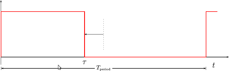 |
In this figure, the
PWM
signal is shown in red. The current time this waveform is positive is given
by tau. The information within the waveform is captured by moving the
transition time back and forth with respect to the center of the period.
With a signal description that simple, generating a PWM modulator is as simple as any good beginner’s assignment should be.
First, you will need a counter. This will count from the beginning to the end
of the interval, and then start over. If we use the handshake pipeline
signaling
strategy, then we’ll need an o_busy (a.k.a. stall) signal to slow down any
logic that is feeding our pipeline. Hence, if we allow for a constant length
interval of COUNTS_PER_INTERVAL clock ticks, the first part of our code
will look like:
always @(posedge i_clk)
	if (counter >= COUNTS_PER_INTERVAL-1)
	begin
		counter <= 0;
		sample <= i_sample;
	end else
		counter <= counter + 1'b1;

always @(posedge i_clk)
	o_busy <= (counter == COUNTS_PER_INTERVAL-2);
Note that we need to compare the counter against COUNTS_PER_INTERVAL-1
to make certain that we have an interval COUNTS_PER_INTERVAL long. Likewise,
we want the o_busy signal to be true for the one clock when
counts == COUNTS_PER_INTERVAL-1, and to do that we need to set it one
clock earlier.
The last step, that of determining whether or not our pin should be on or off, is determined by the simplest comparison:
always @(posedge i_clk)
	o_pin <= (counter < sample);
That’s how you build an audio PWM peripheral.
The problem wih this approach is that audio sounds horrible.
Problems with the traditional development
Let’s spend a moment and discuss all of the problems associated with generating a PWM signal in this fashion. This will help guide our solution later.
The first problem with this algorithm is that the samples need to range
between one and COUNTS_PER_INTERVAL-1. Commonly, samples are represented as
two’s complement
integers ranging from between -2^(N-1) to 2^(N-1)-1.
Converting from
two’s complement
to the samples this algorithm would require is going to require
multiplying by (COUNTS_PER_INTERVAL-2)/2^N and then flipping the sign bit.
While the divide by 2^N can be accomplished just dropping the lower
N bits, this still requires a multiply by
COUNTS_PER_INTERVAL-2.
It would be nice to have an alternative that doesn’t require any multiplies.
The second problem with the standard
PWM
development is that the only way to send a zero is to send a
square wave
with a 50% duty cycle (tau is in the center of the interval). Such a
square wave
is a tone which can be heard when the audio is supposed to be silent, should
the COUNTS_PER_INTERVAL be large enough. Indeed, this “silent” tone can be
very obnoxious on the ears.
The third problem with the development above is that the sample rate must be an integer divisor of the system sample rate. This limits the sample rates that can be created.
Coupled with the sample rate is the difficulty of getting a high dynamic range. More output voltage resolution requires a slower sample rate. However, a slower sample rate brings the nasty audio harmonics into the audio range. For this reason, it can appear impossible to get good sound quality from a PWM output. Perhaps this was the idea, but we’ll do better in a moment.
The final problem with this means of creating an audio signal is that it creates lots of unwanted harmonics, i.e. distortions, in the audio that you wish to produce. We’ll see these when we introduce our improvements in a moment. Our goal should be to reduce these distortions.
Hang on, that’s coming up.
How a PWM fits into a digital audio system
 |
Before we can make an improvement, you need to understand that the ear can only hear sounds between about 20Hz and 20kHz. To be successful, the period of the PWM signal will then need to be well above 20kHz—out of the range of hearing.
Hence, a good audio circuit (audiophiles please forgive me for calling this “good”), following a PWM output, will place a filter on the output to remove anything above 20kHz.
This means that if we can push any distortions towards higher frequency components, then these distortions will get filtered out by the amplifier circuitry (or your ear), and the result will sound more pleasing to the ear.
Can this be done?
A better PWM
Ok, you’ve waited enough, here’s the technique: Bit-reverse the counter before
comparing it with the sample.
Further, we’ll insist that our
PWM
counter have a power of two length so that
the bit reversed counter will take on the same values that the counter would’ve
taken on in the first place. The result is a waveform that is like
PWM,
although technically not a
PWM signal.
It is more generally a
PDM signal,
but unlike the implementation of
PDM
presented on Wikipedia
this implementation is very easy to calculate. Like both
PWM and
PDM
the result will nominally maintain the same number of output clock periods
that a PWM
output would have been on. Likewise, it will also be off for the same number
of clock periods that a
PWM
output would have been off. (Assuming 2^N clocks per interva.) It will
produce the same number of one’s, and
the same number of zero’s. The only difference is that bit-reversing the
counter will cause these one’s and zero’s to be produced in a different order.
I’m going to call this new signal type simply bit-reversed PWM, even though technically it’s not really a PWM signal at all any more.
To understand what’s going on, let’s consider what the traditional PWM output would be for a sine-wave (shown in Fig. 3 below).
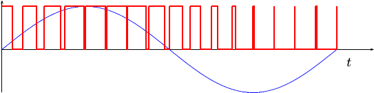 |
Now, let’s take a look at that same sine wave output, but this time we’ll bit reverse the counter before creating our output signal.
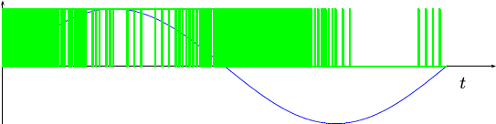 |
From this figure, you can see that there are many more transitions in the bit-reversed PWM signal. Another way of saying this is that the bit-reversed PWM signal has a lot more high frequency content. This extra high frequency content should be easier to filter out with cheap analog circuitry, and hence the remaining audio quality should be better.
Enough of the hand-waving, is this new approach actually better? To answer that question, let’s look at a Fourier transform of the PWM encoded sine wave in Fig. 3, and let’s compare it to the Fourier transform of the bit-reversed PWM sinewave from Fig. 4. We’ll place this frequency comparison into Fig. 5 below.
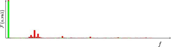 |
In this Figure, the vertical bars are frequency components, running from just above zero frequency at the left to higher frequencies at the right. Their height is given by the magnitude squared of the Fourier transform output values. These are not decibel values. The tone we want to create is represented by the tall vertical bar near the y-axis line. The Fourier transform of the original PWM scheme is represented in red, whereas the Fourier transform of our modified bit-reversed PWM sinewave is represented in green.
Now that you understand the graph, notice the additional red bars to the right of the bar associated with our audio signal (the sinewave). These are distortions. Your ear will hear these distortions, and the result won’t sound like the pleasant tone you wanted.
If you look further, you won’t see any green distortions to speak of. It’s not that they aren’t there, it’s just that they’ve been spread out and spread across a much higher frequency range. Those distortions in green that do remain within the audio range are much smaller in magnitude.
The next step, now that we know how to improve this PWM development, is to build our improved signal and hear what it sounds like.
Building the updated PWM’s logic
Let’s now work through how to code this bit-reversed PWM signal, and make an audio controller using the scheme.
The first step to creating a more pleasing sounding PWM audio waveform is to bit–reverse the counter. If we let our counter be a simple 16-bit number, we can reverse it with a for loop within a Verilog generate statement.
// The bit-reversed (br) counter
wire	[15:0]	br_counter;
genvar	k;
generate for(k=0; k<16; k=k+1)
begin : bit_reversal_loop
	assign br_counter[k] = pwm_counter[15-k];
end endgenerate
The beginning
HDL.
student should remember that for loops in Verilog are not
like for loops in software. This loop does nothing but rename the wires
within the original pwm_counter. It requires no
CPU
instructions, nor
FPGA
logic elements,
to be accomplished. As a result,
there’s no time consumed by the logic this loop creates.
This loop is actually the whole key to the algorithm, and the source of the difference we are going to create. If you’ve built a PWM based audio signal before, you now understand how to build a better one. We’ll keep going, though, just for completeness.
We can then create our output from comparing this bit-reversed counter to the sample we would desire to output.
// Create the PWM output
always @(posedge i_clk)
	o_pin <= (sample_out <= br_counter);
You can find the code to create this type of waveform in my wbpwmaudio repository on GitHub. However, if you look over the code alone, you might find there’s a bit more to it than the code written above.
The first thing missing is the timer to tell the
bit reversed
PWM
audio driver when to switch samples. Unlike our original development,
the wbpwmaudio
core
uses a user-configurable count-down timer. This configurable value is placed
into w_reload_value, allowing us to write our count-down timer as,
initial	timer = DEFAULT_RELOAD;
initial	ztimer= 1'b0;

// ztimer is true for one clock pulse any time the timer restarts.
always @(posedge i_clk)
	ztimer <= (timer == { {(TIMING_BITS-1){1'b0}}, 1'b1 });
always @(posedge i_clk)
	if (ztimer)
		timer <= w_reload_value;
	else
		timer <= timer - {{(TIMING_BITS-1){1'b0}},1'b1};
You might find this code very similar to the count-down timer logic found
in our timing
post.
The big thing you may find different is the parameterized number of bits in
the counter. In this case, the number of bits in the timer counter is
defined by the parameter,TIMING_BITS. Why? Because I needed to be able
to trim the logic within the
S6SoC project down until the project
could fit
onto
Digilent’s CMod
S6.
The other thing you may notice is that the timer reload value isn’t connected to the PWM counter any more. Heresy! No, actually it makes a lot of sense. Because the output bit order is spread uniformly across the sample interval, chopping a value off before it’s had enough time to send all of its bits isn’t something the ear will notice. Further, this allows us to use arbitrary audio intervals, without suffering significant loss.
Incidentally, this simple change renders genering samples easier. Not only can we feed this value two’s complement values now, but we can do so at our favorite rate. What if there aren’t enough clocks to transmit all the bits in this new value? Not a problem, the algorithm will adjust so that it transmits as many bits as you have time to transmit.
In other words, that’s all it takes to generate this bit-reversed PWM signal.
Let’s go one step further, though. Let’s connect this controller to a Wishbone bus, so that we can send values to our core across such an interface.
Adding Wishbone Control
Let’s now turn this into a fairly complete PWM audio controller. To do this, we’ll add a user configurable sample rate, some registers to control the power control wires in the PModAMP2, and a means of sending audio samples to the controller. Finally, we’ll add an interrupt line to let the bus master know that another sample is needed.
A more capable controller would include a FIFO so as to minimize the cost of servicing this controller, but I’ll leave that as an exercise for the student. For now, we’ll follow the development used for the S6SoC, where the whole goal was to minimize the amount of the logic, and leave the FIFO out.
If you’ve never built a wishbone slave before, you might wish to read our previous discussion as a background reference first.
Our first task is going to be creating a reconfigurable sample rate. In a
PWM
system, the sample rate is determined by the number of clocks per sample
duration. We’ll call this number of samples w_reload_value–something you’ve
already seen above. The
wbpwmaudio
code offers two methods of setting this value. These two methods are selectable
at design time via the VARIABLE_RATE parameter. If VARIABLE_RATE is zero
(false), then the timer will always reload its value from a fixed
parameter value, DEFAULT_RELOAD, at the end of every interval. If
VARIABLE_RATE is true, on the other hand, then the timer will reload its
value from a programmable register.
Since we are using wishbone control,
this register will need to be set from the bus any time (i_wb_stb) is high,
indicating a bus cycle, (i_wb_we) is high, indicating a bus write cycle, and
(i_wb_addr) is high, indicating we are writing to the second of two
registers–the timer reload register.
generate if (VARIABLE_RATE != 0)
begin
	reg	[(TIMING_BITS-1):0]	r_reload_value;
	initial	r_reload_value = DEFAULT_RELOAD;
	always @(posedge i_clk) // Data write
		if ((i_wb_stb)&&(i_wb_addr)&&(i_wb_we))
			r_reload_value <= i_wb_data[(TIMING_BITS-1):0];
	assign	w_reload_value = r_reload_value;
end else begin
	assign	w_reload_value = DEFAULT_RELOAD;
end endgenerate
We’ve already seen above how this affects our timer: when the timer runs out,
it gets reset with this value. Likewise, ztimer is set to be true any
time the timer has run out.
This is also going to control when the design accepts the next sample:
always @(posedge i_clk)
	if (ztimer)
		sample_out <= next_sample;
next_sample is a one-sample buffer. It allows the
CPU
or any other
bus mastering
audio controller
a full sample interval in order to reload the value.
Setting this one-sample buffer will be our next step. In this case, we’ll
set it any time a bus write takes place (i_wb_stb)&&(i_wb_we) to the
zero address of this port (!i_wb_addr).
Alternatively, if we are using a fixed sample rate, we’ll ignore the address
and just set the sample. In this case, we’ll set the sample based upon the
16-bit sample value on the input
wishbone bus
data lines.
initial	next_valid = 1'b1;
initial	next_sample = 16'h8000;
always @(posedge i_clk) // Data write
	if ((i_wb_stb)&&(i_wb_we)
			&&((!i_wb_addr)||(VARIABLE_RATE==0)))
	begin
		// Write with two's complement data, convert it
		// internally to binary offset
		next_sample <= { !i_wb_data[15], i_wb_data[14:0] };
		next_valid <= 1'b1;
		if (i_wb_data[16])
			o_aux <= i_wb_data[(NAUX+20-1):20];
	end else if (ztimer)
		next_valid <= 1'b0;
There’s a couple things to notice here. First, notice the negation of bit
fifteen–a 16-bit sample’s most significant bit. This is the
two’s complement
sign bit. Flipping the sign bit is the way to convert
two’s complement values,
ranging from -2^(N-1) to 2^(N-1)-1 to the
offset binary values, ranging
from 0 to 2^N-1, that a
PWM
modulator needs. Second, you’ll want to notice the next_valid logic.
This logic tells us whether or not the sample in our buffer is a valid
sample or not. Upon any write, this value is set high to indicate we have a
valid sample in our buffer. Whereas
any time the sample is moved from the one-sample buffer into the
PWM
modulation code as sample_out, the next_valid bit will be cleared to
indicate that there’s no valid sample in the buffer.
In this code, next_sample is set any time an audio sample is written to the
controller. This is then fed to our output-sample value when the period
ends. We’ll also note, upon setting this value, that the value is
valid (next_valid). We’ll keep this valid signal true until our next_sample
value moves into the
PWM
output processing stage (above) as sample_out.
You may also notice the o_aux value above. I use the bits in o_aux to
control two bits which can then be used to control the gain and shutdown pins
from within this controller. So that we can choose whether or not to send
samples or updated control pins, we require that bit sixteen be set if you
want to update the control pins, otherwise we leave the control pins alone.
At this point, we can move on and examine the values this controller returns from the bus. As in our first discussion of how to make a wishbone peripheral, we’ll set the bus output lines no matter whether we are writing or reading. It just simplifies the logic.
generate if (VARIABLE_RATE == 0)
begin
	assign o_wb_data = { {(12-NAUX){1'b0}}, o_aux,
				3'h0, o_int, sample_out };
end else begin
	reg	[31:0]	r_wb_data;
	always @(posedge i_clk)
		if (i_wb_addr)
			r_wb_data <= w_reload_value;
		else
			r_wb_data <= { {(12-NAUX){1'b0}}, o_aux,
					3'h0, o_int, sample_out };
	assign	o_wb_data = r_wb_data;
end endgenerate
Selecting between which register to output took us one clock, so we’ll wait one clock before acknowledge the clock in order to keep the acknowledgement aligned with the data.
initial	o_wb_ack = 1'b0;
always @(posedge i_clk)
	o_wb_ack <= (i_wb_stb);
Further, the value(s) returned by this routine are always ready. This routine never has a reason to stall the bus. (Repeated writes to the data register will just over-write the buffer value.) So, we’ll just keep the stall line low.
assign o_wb_stall = 1'b0;Finally, we’ll add in one further flair: an interrupt line to tell the CPU when the buffer is no longer valid and can be refilled.
assign o_int <= (!next_valid);While I suppose wishbone support isn’t necessary for every core we present, this core already has it and it was fun to present how a PWM generator might be created as a bus slave.
Conclusion
That just about wraps up this post!
We’ve now gone over and discussed the traditional PWM development, presenting how a PWM signal can be used as a cheap digital to analog converter.
We then presented a new approach to PWM that we called the “bit-reversed PWM” approach. We pointed out how this approach spreads the unwanted PWM harmonic energy into higher frequencies, relieving some of the stress on the anti-aliasing filter. This approach also separated the timer determining the edges of the PWM signal from the sample generator, with the purpose of removing some of the noise associated with the periodic signal associated with no signal.
I have personally listened to the quality of the output of this amplifier. My test signal has been a doorbell sound. The doorbell comes out sounding pure, with no noticable audio distortions.
No, I’m not suggesting this is “professional” audio quality, but it is better than the alternative.
Perhaps I may encourage you to try this component IP yourself, to hear how it sounds?
Hmm … perhaps I should show you instead how this component may be simply and easily be integrated into a basic debugging bus, so that you can hear the sound quality for yourself? That will have to remain, though, as a lesson for another day.
And whosoever shall fall on this stone shall be broken: but on whomsoever it shall fall, it will grind him to powder.