
The ZipCPU's pipeline logic
Now that we’ve discussed some general pipeline strategies, it’s time to take a look at how pipelining can work within a simple, in order, pipelined CPU. Let’s take a look, therefore, at the ZipCPU and see how it handles its pipeline logic. What you’ll see is that the ZipCPU uses a variant of the handshaking strategy we discussed earlier.
If you are unfamiliar with the ZipCPU, the ZipCPU has five pipeline stages, as shown in Fig 1.
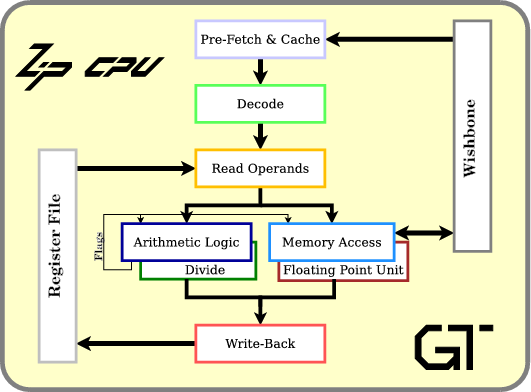 |
There’s the prefetch and instruction cache stage, an instruction decode stage, a read operands stage, an ALU stage and a writeback stage. The ALU stage is also placed parallel to a memory operations unit, a divide unit, and a space for (a still undefined) floating point unit.
As currently built, the ZipCPU is an in-order processor. It’s pipeline structure requires that values going into the write-back unit be strictly in order.
If you choose to look through the main ZipCPU processor’s code, you may find it not as simple to read. That’s because the ZipCPU was written to thread a fine line between two separate purposes. The first, stated purpose, is to be a simple CPU–as measured by the amount of logic used by the CPU. The second purpose is to be a fast CPU. These two purposes are often in conflict. Therefore, the ZipCPU implementation allows you to select the performance you want, and adjust as necessary to fit the amount of logic you have available for a CPU within your FPGA.
Let’s use this as an example, though, in how a CPU pipeline can be created within an FPGA.
Instruction Overview
In order to make the following examples make sense, it might help to understand how the various pipeline stages are supposed to interact. This will make examples easier to understand.
First, almost all ZipCPU instructions have the form:
OP.C Ra,Rb+IIn this example, OP is the operation. It’s a 5-bit field identifying
which instruction is described by this instruction. Think of this as what
the CPU
is being asked to do. Indeed, four of the five OP bits form the
multiplexer selection input within the
ALU as
we discussed earlier.
The C term is the condition. This controls whether or not any value
is written back from the instruction. For example, the
ZipCPU
supports a Z condition which will cause the instruction to only write back
its results if the Z flag is set. The other seven supported conditions are
discussed within the ZipCPU
specification.
The ZipCPU
is primarily a two operand machine. It has no three operand instructions.
Hence, every
ALU
instruction provides two inputs to the
ALU,
Ra and Rb+I and the output gets written back into register Ra.
Finally, and this becomes important for the following discussion, almost
all instructions allow an immediate, usually 14-bits, to be added
to the second register, Rb. Alternatively, an 18-bit immediate value, I,
may replace the ALU’s Rb input so that Rb is not used at all.
So, how does this impact pipelining?
-
In the first stage, prefetch, an instruction is read from memory.
The ZipCPU can run with one of several prefetch modules. [1] [2] [3], and [4]. Each of these modules has roughly the same interface, although the logic within them can differ greatly.
-
In the second stage, the instruction decode stage, the parts of the instruction are drawn from from the instruction word produced by the prefetch stage.
As an example, this stage determines whether or not the instruction even has registers
RaandRbencoded within it that need to be read from the register set. At the end of this stage the CPU, knows:a. what registers it needs to read (
dcd_A, anddcd_B),b. if it needs to read from any register (
dcd_rA, anddcd_rB)c. what the immediate value is (
dcd_I), and if that value is zero (dcd_Iz)d. etc.
-
The third stage, the read operands stage, not only reads
RaandRbfrom the register file, but also addsItoRb. -
The fourth stage calculates the
OPfunction on the values fromRaandRb+I.If this is an ALU, instruction, the
OPfield controls which potential output from the ALU, will be selected.If this is a memory operation, a store will place the value
Rainto memory locationRb+I. A load will read from memoryRb+Iand present the result to the writeback unit.Memory accesses, divides, and multiplies may all take longer than a single clock in this stage. We’ll need to come back and discuss how to handle this later.
If done well, the outputs of this stage, whether from the ALU or the memory unit can go directly back into this stage as inputs if so desired, as shown in Fig 2.
Fig 2: Answers go back into the ALU 
This will take place any time the output of the ALU stage forms the input for the next instruction. Indeed, this is a key requirement for a high speed pipelined CPU.
However, if the output of the ALU gets placed into the
Rbregister input of the next instruction, and if that instruction has an immediate,I, that needs to be added to it (dcd_zIis non-zero), then the output cannot go directly back into the ALU. It will instead need to go back to the read operands stage, causing a pipeline bubble in the process. This other path is shown by the dotted line in Fig 2. -
Finally, in the writeback unit, if the
Ccondition matches, the result is written back into the register set.Conditional branches are detected in this stage. We’ll have to come back and discuss how to handle this within the pipeline later as well.
This is nominally how the ZipCPU handles and uses its pipeline. This simple pipeline, though, has all kinds of hazards—many of which we’ll discuss below.
Pipeline Stalls and Bubbles
Before diving into pipeline specifics, let’s define a pipeline stall.
According to wikipedia, a pipeline stall is a condition where there’s no valid instruction within a particular pipeline stage. Wikipedia declares a pipeline stall to be synonymous with a pipeline bubble.
As the ZipCPU uses the term, a pipeline stall takes place when there is a valid instruction within a particular pipeline stage, but when that instruction cannot move forward.
For example, the ZipCPU divide takes roughly 32-clocks to complete. During these 32-clocks, instructions in the prior stage, the read operands stage, will be stuck there until the divide completes. Likewise, the writeback stage will be idle during this time, being reserved for writing back the results of the divide instruction.
Wikipedia’s definition declares the condition where no valid data is within a pipeline stage to be called a stall. This seems to me to be more of a consequence of a stall, than a stall itself. The pipeline bubble term describes this better, although Wikipedia declares the two terms to be synonymous.
If you watch the pipeline, such as within the demonstration we’ll discuss later, you can visually see bubbles form within it where there are no valid instructions.
Unique Pipeline Needs
There are two basic goals that a CPU has with respect to pipelining. These two goals are common among many pipeline systems:
-
Keep every stage filled.
For example, the ZipCPU is capable of completing and retiring one ALU instruction per clock. All of the pipeline logic within the CPU has been designed so as to keep one instruction completing on every clock.
This is a common goal of any high speed pipeline.
-
Satisfy any pre-requisites for instruction operations.
An ALU operation cannot complete if its values haven’t finished being produced from other parts of the CPU. For example, if register
R0is read from slow memory in one instruction and then immediately used on the next instruction, the pipeline logic will need to stall the second instruction, waiting for the ALU, untilR0is available.This problem is even worse if an immediate is to be added to the value read from memory prior to heading into the ALU. In that case, it’s not just the ALU that needs to stall, but the ZipCPU also needs to stall the read operands stage where that immediate addition takes place. (We discussed this with Fig 2 above)
A CPU, though, has some other pipeline needs beyond the more traditional data flow processing pipeline. Specifically, CPUs need to be able to jump from one instruction in memory to another. This creates some unusual pipeline requirements.
At its most basic level, a
CPU
needs be able to flush or clear its pipeline any time a branch renders
the work done in a prior stage irrelevant.
The worst case scenario is when a branch takes place that can’t be
caught prior to the writeback stage. In that case, the whole pipeline will
need to be flushed, costing the
CPU
one clock per pipeline stage that cannot be completed.
The ZipCPU
captures this logic with the clear_pipeline signal.
Other things can cause sudden pipeline changes as well. For example, what happens on an interrupt (peripheral initiated), a trap (user initiated), or a fault? The CPU will need to start processing instructions from a new location in the instruction stream–that of the interrupt service routine (ISR). The ZipCPU handles this condition by flushing the pipeline on any change of interrupt status. The ZipCPU is also unique in that the interrupt address is kept within an alternate register set. (See the ZipCPU specification for details.
Indeed, lots of things need to change within the
ZipCPU
every time it switches to an interrupt context, or back again.
If you want to trace this logic, feel free to
look for
the w_switch_to_interrupt and w_release_from_interrupt wires. The first
will be true any time the
ZipCPU
switches to an interrupt context, the second will be true anytime the
ZipCPU
switches back.
Now, with all that as background, we can discuss the logic necessary to handle a pipeline handshake.
CPU Handshake
 |
The
ZipCPU
pipeline is controlled primarily with three logic signals per stage:
stalled, valid, and CE, as shown in Fig 3 to the right. The logic is
designed around the idea of processing the data from the previous stage any
time a CE line is set. The basic logic is this: if a stage is not stalled,
and if the previous stage is valid, then the CE line will be set. The CE
control signal is used to determine when to clock the data from the last stage
forward.
Let’s walk though that for a moment.
First, each stage has a condition (or set of conditions) that might stall the prior stage from entering this stage. This is the stall logic for this stage.
For example, the read operands stage will stall any time the
ALU
is already busy, the memory
unit is busy
with a read, or the
divide is busy.
The lines alu_busy, mem_busy, and div_busy are used to capture these
conditions. An exception is made if the memory unit is busy writing a value
over the bus. In this case, mem_rdbusy captures the idea that the memory
is busy with a read and not a write. Likewise, the
ALU
will also stall if the external halt request line is true. (We’ll come back and
discuss this when discussing how to debug a
CPU later.)
Another, less common, example is that the
ALU
will stall any time the condition codes are written to manually–lest the
ALU
write a value back according to the wrong conditions.
In general, though, the stall logic looks like:
assign	stage[n]_stalled = (stage[n]_valid)&&((stage[n+1]_stalled)
		||(things that would stall this stage));
In this case, I’m using stage[n]_stalled to describe the stalled variable
for this stage. If you look within the
ZipCPU,
you’ll find variables named pf_stalled, dcd_stalled, op_stalled,
alu_stalled, and mem_stalled. These variables capture this
logic, together with all of the more obscure reasons why the stalled line
might be made true as well–such as on a debugging BREAK instruction.
Second, if any stage is not stalled, and if the prior stage has valid data within it, then we can step that stage forward.
assign stage[n]_ce = (stage[n-1]_valid)&&(!stage[n]_stalled);If you pay close attention, you might find this looks a lot like the
handshake signal, (i_ce)&&(!o_busy), that we discussed in our last post on
pipelining.
Inside the
ZipCPU,
these various pipeline variables are named
dcd_ce, op_ce, alu_ce, mem_ce, and div_ce. There’s also a similar
master_ce which is controlled from the external debugging interface–something
we’ll get to later.
With these signals out of the way, we can start working through the pipeline
signals. The first registered signal is the valid signal. This signal
indicates whether or not a particular stage has valid data within it.
To get valid data into a stage, the prior stage must have valid data, and
this stage cannot be stalled. Hence, we have the following logic:
always @(posedge i_clk)
	// On any reset or clear pipeline, we clear the stage valid
	// register
	if ((i_reset)||(clear_pipeline))
	begin
		stage[n]_valid <= 1'b0;
	end if (stage[n]_ce)
	begin
		// Otherwise, we accept the data from the previous
		// stage, and operate upon it if necessary.
		stage[n]_valid <= stage[n-1]_valid;
	end else if (stage[n+1]_ce)
		// If there's nothing valid to come in, but the next stage
		// has taken our data, then we are no longer valid here anymore.
		stage[n]_valid <= 1'b0;
Within the
ZipCPU,
the basic valid registers are called pf_valid, dcd_valid, op_valid.
The op_valid signal is also broken into three separate signals, depending
upon which stage the read operands stage moves to next:
op_valid_alu, op_valid_mem, and op_valid_div. Finally, the output
of the ALU/MEM/DIV stage is captured by the alu_valid, mem_valid, and
div_valid signals. Indeed, these signals are used to determine whether
or not valid data is ready to be written back.
One particular difficulty with this language is the idea of an illegal
instruction. Within the
ZipCPU,
a stage containing an illegal instruction has the valid line set high.
This is because an illegal instruction needs to be processed like any other
instruction, and the valid line controls when processing moves forward.
The alternative, moving instructions forward any time valid or
illegal were true, just costs more logic than required.
Each stage has many more logic lines beyond the ones we just discussed.
These can often be treated in a much simpler fashion, though. As a result,
these other signals are often sate based upon the simple stage[n]_ce signal:
always @(posedge i_clk)
	if (stage[n]_ce)
		stage[n]_data <= ... // function of stage[n-1]_data
Those are the basics of how the ZipCPU handles pipelining. Be aware, though, the devil is in the details. There are all kinds of pipeline hazards that you may not expect when first building a CPU.
My best advice for others, when trying to find these pipeline problems, is to methodically debug your CPU using Verilator and some small programs. Use GCC both all optimizations turned on, as well as with all optimizations turned off. The two environments create very different pipeline environments, and programs working in the one may not work in the other. My second piece of advice would be to create a program containing every pipeline hazard you can think of, and to turn this program into a test program for the CPU. You can find the ZipCPU’s CPU testing program within the OpenArty distribution.
Demonstration
I have a wonderful demonstration of all of this that I would like to post, but to see it I may need some help from my readers.
Specifically, the demonstration involves building the ZipCPU distribution, and then running the simtest program within the simulator.
The simulator
allows you to watch how well the pipeline is filled at any given clock, as
well as the ability to “watch” the signals discussed above. Further, by
adjusting the pipeline
parameters,
you can see how the pipeline and
CPU
are affected as the logic within the
CPU,
is increased or decreased. Indeed, you can watch the valid, CE, and
stall lines as they get set and adjusted on a clock by clock basis.
Nominally, the instructions to do this would require something like:
# Install packages necessary to build the simulator
sudo apt-get install bc verilator
# Install packages necessary to build GCC
sudo apt-get install flex bison libncurses5-dev
sudo apt-get install libmpfr-dev libmpc-dev libgmp-dev libmpfr-doc
# Install libelf.  libelf is used to load executable files into both
# the simulator and onto any actual FPGA H/W
sudo apt-get install libelf-dev
#
git clone https://github.com/ZipCPU/zipcpu
cd zipcpu
make
if [[ ! -x sw/install/cross-tools/bin/zip-gcc ]];
then
  echo "GCC failed to build"
else
  if [[ ! -x sim/verilator/zipsys_tb ]];
  then
    echo "The simulator failed to build"
  else
    PATH=$PATH:`pwd`/sw/install/cross-tools/bin
    cd bench/asm
    make simtest
    cd ../../sim/verilator
    # Run the demo
    ./zipsys_tb ../../bench/asm/simtest
    # Press the 't' key to create a system clock 'tick's until things stop
    #   changing
    #   Watch how instructions work their way through the various pipeline
    #   stages at the bottom of the screen
    # 'q' can be used to quit.
    # 'r' can be used to 'reboot' the computer, and start the simulation over
  fi
fi
This is notional only, the above script has not been “tested” … but I think it captures the idea of what I would have you do.
My specific problem is that, while the design works nicely on my own system, I’d love to have some help from others who would like to try running the design on their own systems–so as to get some redundance across operating systems and version differences. If you are interested in trying this, please write be at the address below if you have problems, or perhaps just to tell me of your success. Enough successes, and I’ll write a more complete post about how to watch the ZipCPU pipeline in action.
(Instructions for installing the prerequisites on a Windows machine, using Cygwin, can be found here)
Conclusion
That’s it! The ZipCPU basically uses the handshake approach to handling pipeline stalls that we discussed earlier. A couple extra variables for logic expression allow the ZipCPU to be able to detect and respond appropriately to pipeline hazards, stalling the CPU. anytime it is necessary to do so.
Now that we’ve gone through this example, I’d like to come back and discuss how to debug a CPU running within an FPGA in general. That post has been mostly written for some time, but has been waiting for this background beneath it to be explained.
I’d also like to post more complete instructions for the pipeline demonstration above, outlining how data moves through the various stages of the ZipCPU pipeline. I’ll hold off on the demonstration, post, until I have some confidence that it will work on the greatest number of computers.
For I know that my redeemer liveth, and that he shall stand at the latter day upon the earth (Job 19:25)