
Accessing the registers of a SoC+FPGA
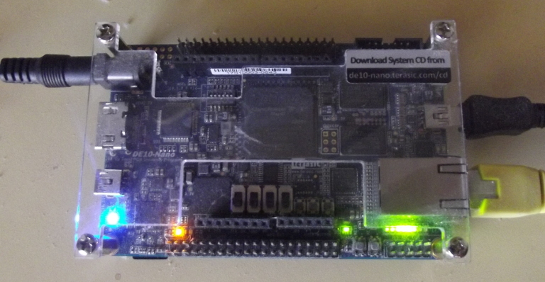 |
Some time ago, I wrote about my experiences with Terasic’s DE10-Nano, a design based around Intel (formerly Altera)’s SoC+FPGA Cyclone-V design. If you’ve never worked with designs like this, the terminology typically separates the SoC (i.e. an ARM) from the FPGA with the terms Processing System (PS, or ARM) and the Programming Logic (PL, or FPGA).
These combined SoC+FPGA designs are an attempt to gain the best of both FPGA and CPU worlds. By combining the two together, the CPU can control the logic taking place on the FPGA. This control includes being able to load designs onto the FPGA from the CPU, and to then control those designs from the CPU using memory-mapped I/O register. The FPGA is in an ideal position to control peripherals and their timing in detail. The FPGA is also in an ideal position to be a data accelerator. Both of these applications require that the CPU be able to communicate with the FPGA at high speed.
 |
The Cyclone-V chip on the DE-10, like other SoC+FPGA designs, has a high speed data path directly from the ARM to the FPGA, and again in the reverse direction as shown in Fig 2. These will form the topic of this article.
Today, I’d like to focus on the ARM side of this connection–the side where the FPGA is controlled by a CPU. We’ll ignore, and postpone for a later day, all of the details associated with building the FPGA half of this connection, and focus solely on the CPU side of this connection. For now, I’ll only say of that connection that I highly recommend you formally verify the FPGA side since it can be so difficult to debug.
Further, I’m going to walk through two examples that can be used for this purpose. The first should work well on any generic microcontroller with no memory management unit (MMU) support, and the second should work not only for the DE-10, but also for any Linux memory mapped interface including Zynq designs, the Raspberry Pi, the Beagle Bone, and even other ARM based memory-mapped I/O register designs.
I should pause to note that there’s a discussion to be had regarding whether or not this code should be done within user space at all rather than in the Operating System. There are strong arguments for both, so I’ll just leave that discussion for another day.
So, without further ado, shall we discuss how to get access to fixed-address registers from within a design?
Fixed Addressing
 |
For your simpler non-Linux
microcontroller
based designs, the interface is very straightforward and simple, though it
requires knowing about a part of the C language that isn’t usually used
outside of hardware programming: the
volatile
keyword.
Suppose you have an interface at a known address, 0xc045010, shown as the
“user pointer” in Fig 3. on the right. Let’s pretend
that it’s a reference to a device controller that occupies four 32-bit words
in our address space. A good example of this might be the
WBUART serial port. That peripheral has
four word-length registers controlling it.
typedef struct  WBUART_S {
	unsigned	u_setup;
	unsigned	u_fifo;
	unsigned	u_rx, u_tx;
} WBUART;
You’d like to be able to read from these registers within your own code. To do that, you need a pointer to them. The way to create a pointer to a fixed address in C++ is,
static volatile WBUART *const uart = (WBUART *)0xc045010;Let’s parse this line.
At the most basic level, we have just described a pointer to a
WBUART
structure in memory, and we’ve named this pointer uart and given
it an initial address of 0xc045010 to point at.
Peeling the onion back one further, the const dictates that this pointer
references a constant location in the address space. It cannot
change. This is appropriate if ever the device in question will always have
the same address space location. Hence, we have a WBUART *const uart. In
this declaration, order matters. const WBUART *uart would have declared a
pointer to a constant WBUART uart structure. That’s not what we want. We
want constant pointer to a structure of elements that isn’t necessarily
constant.
The next part of this definition is the
volatile
part. This instructs the compiler that the value at this location in memory
might change apart from the program it is compiling changing it.
To explain this, imagine you want to transmit a character. In the
WBUART
interface, the 0x0100 bit of the transmit register returns a status field
indicating whether or not the register is busy. If this bit is set, the
transmitter is busy or the transmit queue is non-empty. If this bit is clear,
then the interface is idle. For this task, let’s wait until the interface
is idle and then write a byte out of the serial port.
void	txchar(int ch) {
	// Wait for the transmit port to become available
	while(uart->u_tx & 0x0100)
		;

	// Send the character out the transmitter
	uart->u_tx = ch;
}
This sort of loop, waiting for something to happen, is called
polling.
It is one of several ways to wait for an event within a
CPU.
In this case, we are waiting for the
WBUART
transmitter to become idle.
A compiler might look at this code an notice that nothing within this
function is modifying uart->u_tx. It might then consider itself justified
in treating this value as a constant, and pulling it out of the loop.
void	txchar(int ch) {
	int	v;
	v = uart->u_tx;
	while(v & 0x0100)
		;

	// Send the character out the transmitter
	uart->u_tx = ch;
}
This “optimized” implementation will only read from the peripheral register
once, and then either hang forever (if the interface is initially busy),
or move in. This is clearly not what we want, since with this “optimized”
implementation we’ll never know when uart->u_tx changes!
From the compiler’s standpoint, this optimization makes sense: you read the value, and it doesn’t see anything changing it, so it only reads the value from memory once.
The compiler needs to be told that this value can change for reasons other
than the instructions it can examine within your code. This is the purpose
of the
volatile
keyword in our definition above.
What about the static term? This tells the compiler that only the code in
the current file will reference this value. This keeps the compiler from
placing this constant value in global memory somewhere. The address can
then be compiled into the object code as a fixed immediate value.
For designing interfaces to match most simple SoC design components, this is enough. If on the other hand the CPU has a MMU, like most ARM and x86 processors (and more), then the fixed address may not be accessable to the program, or it may be accessable at a different virtual address. In these cases, the above approach will not work and you will need to get some help from the Operating System.
Dealing with the MMU - Designing the Interface
Declaring a constant pointer value, such as we did in the last section, isn’t
sufficient to access memory in a system that permits a virtual address
space.
In that case, every process might reference the same
physical address
using
a different pointer value (virtual
address).
The trick in this case is
determining how to get a virtual
address
that will map to the
physical addresses of the
peripheral registers
in question.
 |
When we built our debugging
bus, we used the
routines readio(addr) and writeio(addr,value) to access registers within
a traditional
FPGA,
see Fig 4. To read a register, one might write:
value = m_fpga->readio(addr);In a similar fashion, you could write to a register controlled by a debugging bus by writing,
m_fpga->writeio(addr, addr);I’m going to try to maintain this interface (somewhat), although that’s really more than is required when interacting with a SoC+FPGA.
In the Intel SoC+FPGA design, there are a couple of memory regions that can be mapped like this. For the purpose of this example, let’s focus on the light-weight interface, although aside from changing a couple of constants in the design below, the result would be the same for any other shared memory region, such as the heavy weight interface or the fixed ARM internal peripheral registers.
So let’s design the C++ header file necessary to work with such an interface.
#ifndef	LWMAP_H
#define	LWMAP_H

#include <assert.h>
#include <stdint.h>
#include "hps.h"
We’ll call our interface LWMAP, since it is going to map the lightweight
memory region of the
Cyclone-V SoC
on the
DE-10 Nano.
class	LWMAP {
	int		m_fd;
	volatile uint32_t *m_base;
	uint32_t	m_offset;
We can look up in the
Cyclone-V
device handbook, HPS-FPGA Bridges chapter,
the region of
physical addresses
assigned to this lightweight
memory map.
This region ranges from 0xff200000 to 0xff400000. It references an
area within the
FPGA
side of the design that the SoC portion of the chip can interact
with. We’ll label the first address of this range the LW_REGS_BASE address,
and the number of addresses within this range the LW_REGS_SPAN. We’ll also
define a third value, LW_REGS_MASK, that we can use to force an address to
be in this range–even if it is outside of the range.
	static const	uint32_t	LW_REGS_BASE = 0xff200000,
					LW_REGS_SPAN = 0x00200000,
					LW_REGS_MASK = LW_REGS_SPAN-1;
The next step will be to get a pointer that we can then later use to address
the physical address range.
We’ll place this pointer into the m_base value above, and we’ll do it when
we instantiate or LWMAP object. We’ll come back to the details of this in
a moment, since in many ways these details are the critical piece of this
whole post.
 |
We’ll use the name APPCODE_BASE to reference the location of our user
peripherals within the
FPGA
address space. In general APPCODE_BASE will
lie between LW_REGS_BASE and LW_REGS_BASE+LW_REGS_SPAN. This is one
of those values provided to my design from the Intel Platform
Designer.
Since I chose the name AppCode for my design, short for the very generic
“application code”, the name of my application design is APPCODE_BASE.
public:
	LWMAP(unsigned offset = APPCODE_BASE);
	~LWMAP(void);
Our first function will be to write to this memory mapped I/O region. Given an address within this space and a value, let’s write the value to our address. Since AutoFPGA generates octet addresses, we’ll need to shift our address right by two in order to get the address of 32-bit word. (GCC will optimize this away.)
	void	writeio(const uint32_t addr, const uint32_t value) {
		unsigned	av = ((addr + m_offset) & LW_REGS_MASK)>>2;
		m_base[av] = value;
	}
The process of reading from a register within this memory mapped I/O
region is nearly identical.
However, instead of writing value to the register, we’ll just return the
value at that address.
	uint32_t	readio(const int addr) {
		unsigned	av = ((addr + m_offset) & LW_REGS_MASK)>>2;
		return m_base[av];
	}
It might be nice to just simply write pic_value = lwmap[R_PIC]. This
requires a fairly trivial overload of the [] operator.
	uint32_t	operator[](const int addr) {
		return readio(addr);
	}
Sadly, these writeio and readio operations are only so useful. In many
ways they don’t feal like the natural way of accessing an interface. For this
purpose, lea(addr) calculates and returns the effective address of addr so
it can be used without writeio and readio.
	void	*lea(const int addr) {
		char	*base = (char *)m_base + APPCODE_BASE;
		return base + addr;
	}
};

#endif	// LWMAP_H
How would we use this interface? In just about the same way we did before
when we were working with the debugging
bus.
First, at the beginning of any application, we’d create an object
of class LWMAP. Then we could repeatedly read a register
from the interface.
LWMAP	*gbl_lwmap;
int main(int argc, char **argv) {
	gbl_lwmap = new LWMAP();

	... other main functions

	delete	gbl_lwmap;
}

void	txuart(int ch) {
	// While busy
	while(gbl_lwmap->readio(R_UART_TX) & 0x0100)
		;

	gbl_lwmap->writeio(R_UART_TX, ch);
}
Of course, if we wanted to use the lea approach, we could simplify this code
further.
void	txuart(int ch) {
	volatile	*uart_tx = gbl_lwmap->lea(R_UART_TX);

	while(*uart_tx & 0x0100)
		;

	*uart_tx = ch;
}
The R_UART_TX peripheral register is used here for illustration
purposes only. Your design may, or may not, have an R_UART_TX register
depending on whether or not you put one in there.
Of these two approaches, readio(addr) vs using lea(addr), I’m torn between
which I like more. The lea(addr) approach is simpler to read, while the
readio(addr) is easier to use if you want to run your software on a design
within a Verilator simulation.
This is what we want to accomplish: the ability to read or write memory mapped I/O registers from within a process running in a virtual address space. The only question remaining is, how do we set this up in the first place? That’s the topic of the next section.
Implementing the interface
The secret sauce to making this entire design work lies in the
LWMAP constructor that we just glossed over above. Let’s take a moment
to look through and understand it now.
We’ll skip past some useful header includes.
#include <stdio.h>
#include <stdlib.h>
#include <unistd.h>
#include <assert.h>

#include <sys/mman.h>
#include <sys/types.h>
#include <sys/stat.h>
#include <fcntl.h>
// hps.h is built by Intel's sopc-create-header-files program
// It defines some of our constants for us.  You may or may not
// need it in your design.
#include "hps.h"
#include <time.h>

#include "lwmap.h"
With that out of the way, we can build our constructor method.
LWMAP::LWMAP(unsigned offset) {
	m_offset = offset;
This constructor will depend upon the /dev/mem interface within the
Linux system. This interface will
give us access to the raw physical address
space. Hence,
we’ll start by opening it.
	if( ( m_fd = open( "/dev/mem", ( O_RDWR | O_SYNC ) ) ) == -1 ) {
		perror( "ERROR: could not open \"/dev/mem\", " );
		exit(EXIT_FAILURE);
} |
Our next and critical step will be to map this “file”, that is the
physical address space
device of the system, into a region of memory within our
process. In our case, that memory starts at LW_REGS_BASE
and continues for LW_REGS_SPAN addresses. We’re creating a shared memory
map, so other processes can use this memory as well (watch out for
concurrency issues!),
and we’re mapping our file (i.e. the memory) based upon the file descriptor
m_fd.
This is done with the mmap system call.
	m_base = (uint32_t *)mmap(NULL, LW_REGS_SPAN,
		(PROT_READ|PROT_WRITE),
		MAP_SHARED, m_fd, LW_REGS_BASE);
This gives us an address, m_base, that we can then use to reference the
LW_REGS_BASE physical
address.
Offsets from that address, up to LW_REGS_SPAN in
distance, will continue to map to this space.
The last step is to check for errors, and exit if this operation failed.
	if( m_base == MAP_FAILED ) {
		perror( "ERROR: mmap() failed, " );
		close( m_fd );
		exit(EXIT_FAILURE);
	}
}
Once you are all done with this interface and no longer need access to any of the peripheral registers from within your application, you can release the memory mapped region. and close the file descriptor.
LWMAP::~LWMAP(void) {
	if( munmap((void *)m_base, LW_REGS_SPAN ) != 0 )
		perror( "ERROR: munmap() failed, " );
	close( m_fd );
}
That’s the basic concept: map a peripheral residing at a physical address onto a virtual page within your processes address space, and then access it like you would any other variable. Writes to that address will write to the peripheral, and reads will read from it.
Conclusion
Normally, I focus on FPGA issues when designing in Verilog. Today’s post has been a bit different. It represents the other half of the FPGA+CPU processing world. If you want to access an FPGA core via a memory-mapped I/O register from C or C++, you’ll need one of the techniques mentioned above.
While I’d like to say that this process is simply and easy, I originally learned it by word of mouth, and then later struggled to find this information when I looked for it. Since this information is so important for FPGA+CPU designs, I’ve chosen to include it here.
Before we leave this topic, though, let me just ask: Did you catch the reference to how software could be written to run on both the CPU connected to the FPGA as well as from Verilator? That will be important if you ever need to work with a design like this.
Salt is good: but if the salt have lost his savour, wherewith shall it be seasoned? It is neither fit for the land, nor yet for the dunghill; but men cast it out. He that hath ears to hear, let him hear. (Luke 14:34-35)