
Your soft-core CPU won't boot. Where should you start debugging?
When I first decided to start Gisselquist Technology, one of my first internal projects was to see if I could get the Linux kernel to boot from a read-only file system–to promote longevity on a flash device, using a kernel that I could swap out remotely at a later time via a call to kexec(). I intended to do this using a Beagle Board Black, and then to sell the capability to a customer as something they could do with their own internally developed boards.
So, I made a bunch of kernel configuration changes, and then tried to boot my newly configured kernel.
Nothing happened.
I just stared at a blank screen.
At the time, I had no idea where to start.
Since that time, I’ve gone on to build my own CPU. In other words, I’ve now had to deal with this problem many times over, where I “start” my CPU and nothing happens. No, I haven’t gone back to the Linux kernel, but I’ve still had the same basic problem.
There is one key difference, however: with a soft-core CPU, 1) I know my hardware (I never knew the ARM that well), and 2) I can run a simulation of that hardware and get a trace leading me straight to the problem. (Yes, this is a painful approach, but it is a reliable one.)
So, let me offer you some of the lessons I’ve learned while trying to debug
the startup of the ZipCPU.
Specifically, how shall the CPU be debugged between when it is released from
reset and the first (successful) call to printf()?
How to debug a boot failure
So, let’s look into how one might debug a “boot failure”. In this case, by
“boot failure”, I mean that you’ve “loaded” both your soft-core CPU either
into simulation
or onto an FPGA, and your program onto your memory device
and then something goes wrong between releasing the CPU from
reset
and the first console output. The question here and now is, how do you
debug that? I mean, a CPU represents a lot of logic to dig through, and
there’s a lot of software between reset and main(). How do you go about
narrowing down the problem to find the bug?
Here’s some of the approaches I’ve found valuable.
-
Start at the instruction fetch
My first step is almost always to look at a simulation trace of the instruction fetch.
For this, you’ll first need a hex dump of the program you are trying to run. I usually get this from
objdump -S -D <program>. Indeed, I use this command so often, I have a common “make” target that I will use to produce this dump file.Now, looking at the dump file, open a simulation trace and look at the address and value of the first several instructions coming from the instruction fetch and going to the CPU’s core. These address/value pairs should match a dump of your executable file.
If they don’t match, that should tell you where to look next:
-
Reset problems
Are you getting any instructions from the instruction fetch at all? If not, you might have a bug in your reset control. Does the CPU come out of reset at all? If it does, does it come out of reset reading from the right address?
It can be a challenge to get a CPU, configured to boot from a flash memory address, to start from a different address describing some other memory that might be easier to work with–such as block RAM. I often do this to initially verify the CPU, before verifying the flash memory, but getting a program to load and start properly from somewhere other than the reset address can be a true test of both the loader and the CPU’s debugging port.
-
Loader
Did your software get loaded into the right place? That is, if the CPU is coming out of reset properly, and if it is reading from the right addresses, is it getting the right values? If not, then this is worth chasing down through the VCD trace. You might find that you haven’t loaded the right values into memory in the first place. (Or … you might also find that either your instruction fetch unit, your interconnect, or your memory controller are broken ….)
In my case, I often need to be reminded that the ZipCPU is a big endian machine while my host computer is a x86 type of little endian machine. Sometimes a translation is required between the two.
-
 |
-
Memory controller problems
Before you start your CPU, it’s often worth double checking the load interface. After writing to address XYZ, for example, can you read the same value back from address XYZ that you have just written to it? This problem may be indistinguishable from a loader problem. In both cases, values will be read from memory, but they won’t be the right values.
To tell the difference between loader and memory controller problems, pick one address that the fetch returns in error and track what’s written to it. If the loader puts the right value into it, but the memory controller returns something else, then you know to look into your memory controller for the bug. We’ll come back to this again in a moment.
 |
You can often dig into this bug using a debugging
bus: While holding
the CPU in
reset,
write to the memory that will hold it’s program and then
read the memory values back out. They should match. This doesn’t always
work, however, since the CPU might use types of accesses to the memory
that the debug bus
doesn’t support–things like
ARLEN>0 or ARBURST=WRAP–but
it’s at least a good start.
 |
-
Bus addressing
There’s always the possibility that you have an error in how the bus interconnect was set up. Perhaps the bus interconnect is routing the CPU’s reset address to the wrong slave, perhaps you have the wrong number of address wires driving the slave. Either way, you’ll see this problem when tracing the instruction request from the CPU back to the bus slave responding to it.
-
CRT0 is just a bunch of memory copies. Look for the loops.
The first piece of software any CPU starts is often known as CRT0. This is the software that sits between reset and main(). This is the software responsible for placing your
main()program into memory.
 |
The first thing CRT0 needs to do is to configure your RAM or ROM controllers. The next step is usually a series of memory copies.
On many computers, CRT0
is written in assembler. While I tried to avoid that with the
ZipCPU, there’s still a small
assembly routine required
before I can transition to the C function that performs the actual
memory copies–a function I’ve named _bootloader.
The small assembler script is responsible for any hardware configurations
necessary to get the RAM running, for then setting the
stack pointer,
and finally for calling the _bootloader function. This is marked
as step 1 in Fig. 1 above. Because this step is so small, typically
less than 20 instructions, it can easily be debugged using the
VCD trace file if necessary.
This is not the case with the step that follows.
The first step of the _bootloader function, marked as step 2 in Fig. 1,
is a big memory copy. It will copy instruction memory from ROM to RAM,
and then again to copy any pre-initialized global variables from ROM to
RAM.
Debugging this memory copy can be a challenge.
So how do you go about debugging a memcpy()? That piece of software is just a huge loop! The CPU may be copying millions of bytes, and so staring at this trace can quickly get frustrating.
 |
Here’s the trick: instruct your VCD viewer (I use GTKWave) to display the CPU instruction address register, often called the program counter or PC (for short), as an “analog” waveform. Then zoom out. Watch how this waveform changes, and you’ll quickly find where the loop begins and ends.
-
Make sure the bus doesn’t freeze up while reading. This is often a sign that you didn’t formally verify a bus component. It could be either CPU’s memory controller, the hardware memory controller, or the interconnect between the two.
-
Look for loops that do not end. This is often a sign that either the CPU can’t execute the instructions you think it can, or that the CPU is reading the wrong data from memory.
-
Now debug the beginning and ending of these loops
If the first word is correctly copied into memory but the last word is not, then bisect the loop as many times as necessary to find the bug. Perhaps you are copying from a device that isn’t as big as you think it is? Perhaps you have an incorrect copy size?
One problem I’ve often had here can be traced to trying to use one CRT0 routine for many hardware situations. For example, sometimes I’ll have a high speed (block RAM) address range to copy memory to in addition to a (slower speed) SDRAM address range. To tell the difference, I need to check this block RAM address against NULL after linking. However, GCC will often assume the address is not NULL (because of how I’ve declared it), and so skip this comparison. In this case, the CPU didn’t run all the memcpy()’s I had requested. Looking over how CRT0 got translated to assembly should show you if the NULL checks were removed by the compiler or not.
 |
After copying program memory and initial variables, the _bootloader
routine then needs to zero
out.
the BSS data segment. This basically
requires a glorified
memset(),
which can be debugged in the same fashion as the
memcpy() above.
-
Verify the instruction fetch following the CRT0 routine
Once CRT0 completes, that is once both the (alternative) memcpy() and memset() functions complete, the CPU should jump to the beginning of
main(). This is illustrated as step 4 in Fig. 1 above, and shown in Fig. 2 below. Therefore, let’s go back to the instruction fetch and see that it does so.Does the CPU return from the
_bootloaderproperly? Or did the return address get overwritten somehow?Are the instructions provided to the CPU the correct ones?
In one case, I used the DMA to copy data from the flash to a DDR3 SDRAM via Xilinx’s DDR3 controller. When I struggled to get the ZipCPU software to work, I called a software serial port output routine from within CRT0 to help me debug what was going on. In that case, the serial port output routine I used wanted to insert carriage return characters before newlines, and so it needed to know if the last character was a carriage return. This value was supposed to be kept in SDRAM memory–the very memory I was trying to use and load. This shouldn’t be a problem, I reasoned, since at most I might output an extra carriage return, and the memcpy() routine would eventually overwrite this value with the correct one anyway.
The problem, however, was that using this memory region caused the CPU to read memory into the data cache before the DMA completed. This left me with with a corrupt copy of data memory in the cache once the
_bootloadercompleted. In other words, don’t forget to clear the cache once the DMA completes any memory copies.
-
SIM instructions
Many CPU’s, to include both OpenRISC and the ZipCPU, have special simulation only instructions. These are basically NOOP instructions that will cause the CPU to perform a special task in simulation only. In the case of the ZipCPU, the instruction
NOUTcan be used to dump a character to the simulation console. The instructionNDUMPcan be used to dump a register’s value to the console. The ZipCPU assembler also understandsNSTR, which can be used to create a series ofNOUTinstructions to send a more readable string to the simulation console. If these instructions are left in the code when it runs in actual hardware, then they will simply be ignored like any other NOOP instruction.How can you use these? You can use them to pepper your CRT0 function with these instructions, and therefore know how far your CPU got in the bootup process before it died.
In my case, I’ve done this often enough that the ZipCPU’s
_bootloaderfunction has the appropriateNSTRcommands (commented) throughout, so I can uncomment these if necessary to tell how far it got in the loading process.
-
Use the debugging bus to your advantage
I recently had the opportunity to test both a PSRAM and a HyperRAM driver with the ZipCPU. In both cases, however, the memory needed to be configured properly before it could be used. This meant that I needed to modify the CRT0 function so that it first configured the memory, and the memory controller, before attempting to copy the CPU software to memory.
To get this right, I first fired up the hardware and used the debug bus to read and write hardware memory controller configurations. Any problems were debugged using the WBSCOPE until the memory fully worked. Then, with the same debugging bus, I verified that I could read and write values to this memory using the configuration I was testing. Only after I tested these memory configurations did I then tell the CPU to invoke them from its CRT0 function.
 |
The problem was actually a bit worse, though, since I wanted to reconfigure the flash memory controller that was responsible for reading the initial CRT0 software. This controller naturally started in SPI mode, but I wanted to reconfigure it to run using XiP in QSPI mode. (Normally, my flash controller does this on startup, but I was testing an ASIC controller that day that didn’t have such an option.) That meant I needed to:
-
Configure the external RAM
-
Copy a small subroutine to the external RAM. This got copied to the same RAM location that
main()would run from later. -
Using that small subroutine, take the flash driver off-line and reconfigure it
-
Return to the original CRT0 function, to now perform the memcpy()s as normal, but this time with a flash running in QSPI XiP mode
-
Make sure I flushed the instruction cache, now that my (own) program memory had changed.
Debugging this was a bit of a pain, but still it was all quite doable. The trick was figuring out how to debug the small subroutine, running in RAM, that was reconfiguring the flash driver. For that, I used the ZipCPU’s BREAK instruction to force it to halt mid-run, where I could inspect what the CPU had accomplished.
-
CPU Break instructions
The ZipCPU has a BREAK instruction. Other CPU’s often have something similar. Sometimes an illegal instruction gets repurposed to accomplish the same thing. The ZipCPU uses its BREAK instruction for debugging. When/if the CPU hits a BREAK instruction, it will halt and wait for the debugger. At this point, I can step in and check the ZipCPU’s register values and any hardware configurations. This is really powerful. For example, you might:
 |
-
Make the first instruction of CRT0 a BREAK instruction. If the CPU hits the break, you know it managed to 1) boot from the right address, and 2) read the right instruction at that address. (While it’s possible you might still read the right instruction in spite of these being in error, this would break the fundamental assumption of all debugging.)
This is a big help, especially if you are stuck debugging the CPU from hardware.
-
Place a second BREAK instruction after configuring memory. Now go in and check: was the memory configured correctly? Can you still read and write your memory via a debugging bus? If not, then back up and fix your bug.
In the ZipCPU’s case, the debugger isn’t (yet) smart enough to handle more than one BREAK instruction. I will therefore recompile the software without the first BREAK instruction, but now including the second one.
-
Place another BREAK instruction after each of the various memcpy() functions within CRT0. Are each of these BREAK instructions getting hit? When they are hit, has the memory that was supposed to be copied been copied properly? I usually just check a couple of addresses: the first three and the last three. I tend not to check the middle unless these first and last ones are too repetitive to provide me with any confidence that the copy was done properly.
-
Make the first instruction of
main()a BREAK instruction. Does the CPU get that far?
Let’s back up to our original list and keep going. For example …
-
What if your CPU doesn’t have a break instruction?
If your CPU doesn’t have a break instruction, sometimes you can get away with a “branch to the current address” instruction, and so create a very tight loop. While it’s not quite the same thing, it can still work for this purpose.
If your CPU doesn’t have a debug access port to read and write registers from, then you may need to spend a lot of time doing the same thing with LEDs. While slower, it’s still doable.
 |
-
Console output, but without the console device driver
If you can get to the BREAK instruction at the beginning of
main(), then you are almost there. Once you get this far, if you are still not there then the problem must exist betweenmain()and the first console output.The next check, therefore, is to make sure the console even works.
There are a couple of problems you might have here. For example, is the console port properly connected to the bus? Is it at the right address?
For this, you can again use the debugging bus. Use it to write to the console device while the CPU is halted. Do the values you write get written to the CPU’s console? If not, then pull it up in the simulator and figure out why not.
If it fails in the simulator, then you should have all the information you need to know how to fix it.
If it works in the simulator, but not in actual hardware, then check that the right IO pin is connected, and that the serial port is configured for the baud right rate. (You can read about other reasons why a design might work in simulation, but not in real hardware, here.)
This particular bug is actually a fairly rare bug for me, since I typically use the serial port for the debugging bus. So, in my case, if I have the debugging bus running in the first place then I’ve already debugged the serial port’s hardware. I know, for example, that I have the right IO pin, the right baud rate, the right parity, the right number of bits per character, etc.
Once the raw serial port works, in simulation first and then hardware, and
printf()still doesn’t, then it’s time to debug the standard library. For this, I’ve been known to add more SIM instructions, eitherNSTRorNDUMP, into the library to trace it through it’s operation and find out where it’s failing.Once the stdio library works (in simulation), but still fails in hardware, the next step would be to add serial port accesses to your design that bypass the stdio see where the design is failing. I have a special set of functions, I call them
txfns, that I use for this purpose. They’re designed to be as light and as simple as possible, while writing outputs to the serial port. Using them, I can output strings and hexadecimal numbers directly to the serial port. That’s usually enough to debug the stdio library. You can think of these functions as hardware replacements toNSTRandNDUMP, since that’s how I typically use them.You could also use BREAK instructions here. Again, the goal is to both figure out where the software is going as it works its way through the library, as well as to dump enough values at any particular point along the way so that you can “see” what’s going on.
 |
-
Once you get to the console output, things get easier
Debug by printf is a thing. It may not be ideal, but it does work. When compared to debugging a blank cursor, debug by printf() will feel like cooking with gas.
The task of this article, however, has been to illustrate how to this far in the first place.
CRT0 Example
Just for understanding, let’s walk through this process by examining how the ZipCPU would go about running Hello World. We’ll look at this from simulation traces, all drawn from the ZBasic (simulation only) distribution, and I’ll show you some valuable things you can notice from these traces alone.
Our first trace shows an overview of what Hello World would look like from a GTKWave trace standpoint. It shows the CPU from after reset, through loading Hello World, running Hello World, and then cleaning up and closing the simulation. In this case, “cleanup” is another way of saying, “waiting for the serial port to finish its writes.”
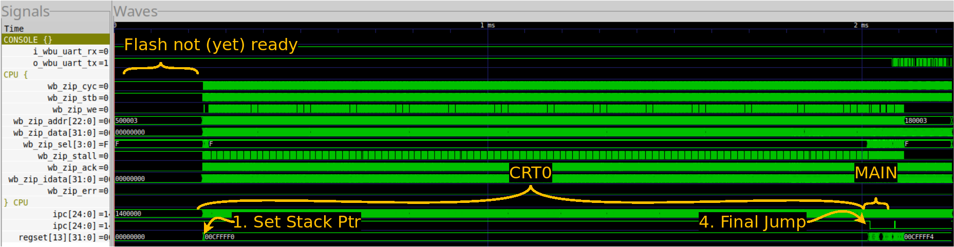 |
Let me walk you quickly through the traces shown in Fig. 2.
The first two traces are either the serial port’s input or its output. As you may recall, serial ports idle high, so here you can see that the outgoing serial port wire is idle for most of the trace, until it finally sends the “Hello, World!” output out.
In the particular configuration shown here, the
ZipCPU has been configured to drive the
Wishbone bus from
either its instruction or its data cache. An arbiter has already selected
one of these two, but you may watch it change from one to the other in
traces to follow.
AutoFPGA has labeled the ZipCPU’s bus
signals with a bus_component_* prefix, in this case wb_zip_. As you
might expect, the first access, following reset, is to read the first
instruction. This is where our figure starts. This access has been held up,
however, until the Quad SPI flash
controller
finishes configuring the external flash device (model) for eXecute in
Place (XiP) Quad SPI mode.
The “ipc” trace shows the
ZipCPU’s
Program Counter (PC),
or more specifically the
supervisor’s
PC within the
ZipCPU. (Another register, upc,
captures the user
PC.)
I’ve also added the ipc register to this display twice. The first
trace
shows it in its default hexadecimal display setting. A quick glance will
illustrate this trace is generally unreadable unless you zoom in so far you
lose all of the surrounding context. The second ipc trace is set to analog
mode. Here you can see very distinctly where the CPU jumps from flash memory
to the block RAM used by the ZBasic
distro for most of its operation.
This is the indication that the ZipCPU
has just began running
main().
(If you look closely, you’ll also see where
main()
completes and returns control to CRT0.
The final trace is that of the
stack pointer. Since the
stack pointer
is just a generic ZipCPU register, and
specifically register 13,
that’s why it’s listed as regset[13][31:0] on the trace. The big thing to
notice here is where the stack
pointer first changes. This is
your indication that the CPU has started running
CRT0.
To see more, however, we’ll need to zoom in a bit.
Let’s start by zooming into the first section of the CRT0 area. In this case, we’ll zoom in a lot.
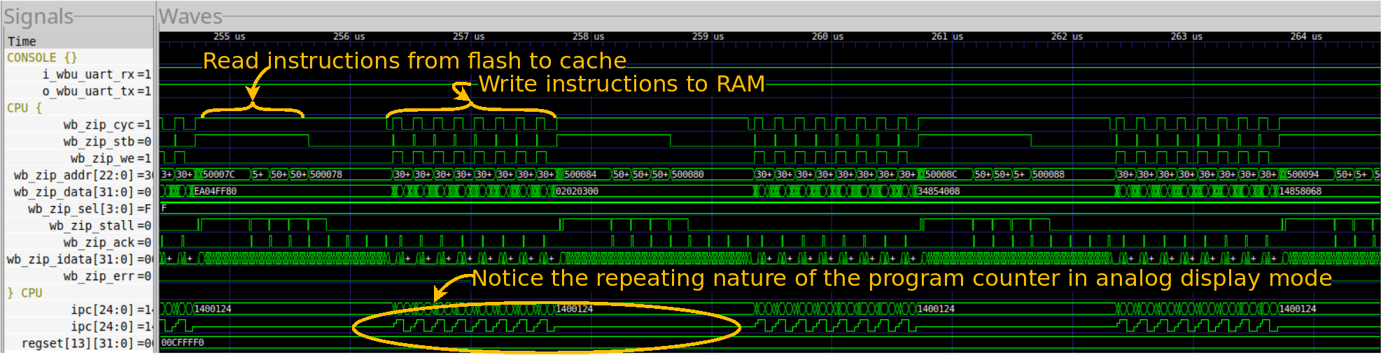 |
The first thing you’ll notice is that the ipc register shows clear looping.
This is to be expected of a memory copy loop. It is a loop, after all.
The next thing you’ll notice is that this loop takes place in sections followed by pauses. This is caused by the data cache. Every pause you see is a cache miss, where the data cache reads another cache line from the flash. The ZipCPU then writes the cache line to RAM. Since the ZipCPU’s data cache implementations are all write-through caches, writes to memory also go immediately to the bus. These are the busy portions of the loop.
Finally, you’ll notice that the stack pointer is constant throughout this whole section. That’s an indication that it’s all taking place within a single function.
The second big section of this CRT0 operation where where the BSS segment is cleared to zero. You can see this in Fig. 4 below.
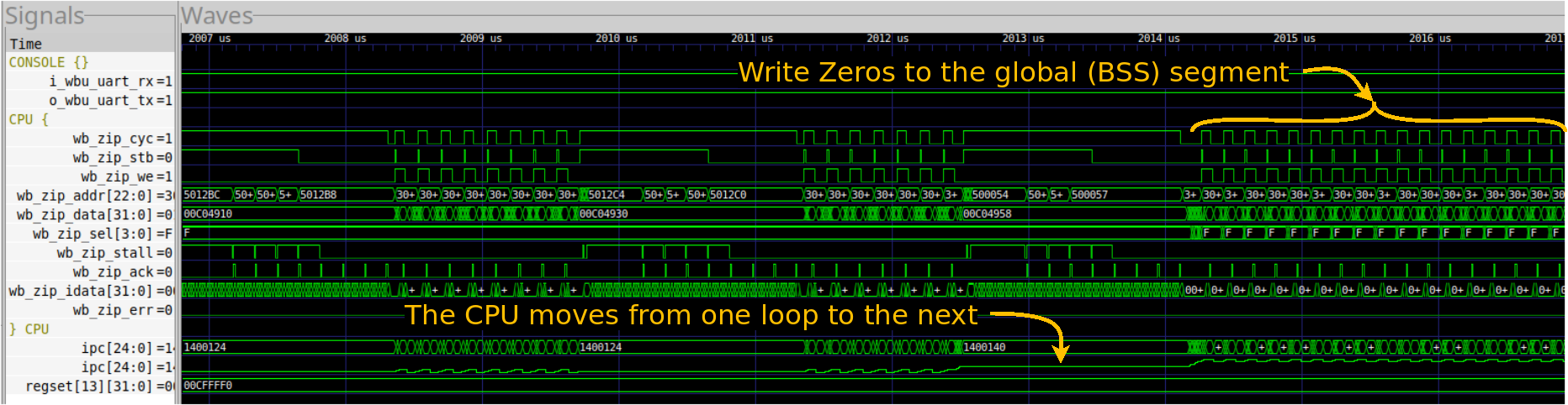 |
In this case, I’ve zoomed in around the transition from the instruction copy to where the ZipCPU starts zeroing the BSS segment. The first thing I’d like you to notice is how easy this transition is to see from the ipc trace. Indeed, the trace suddenly changes shape. Sure, the rest of the trace changes shape as well, but if we zoomed out any more you might miss this and only see the ipc change.
As with the last section, the shape of this section is primarily driven by the data cache. This BSS memset() loop just writes to one value of memory after another, with each value passing straight through the cache to memory.
What you may not notice is that there haven’t been any requests of the bus for instructions. If you look closer, however, you’ll see that’s not quite true. Just before the memset() loop, there’s a cache request–this time from the instruction cache, to get the next eight instructions. These are sufficient to then run the memset() function from cache alone. Hence, there are no more instruction requests of the bus until this loop exits.
Just to show one final example of looping in traces, Fig. 5 below shows the activity on the bus associated with the serial port while the design finally sends “Hello, World!” to the console.
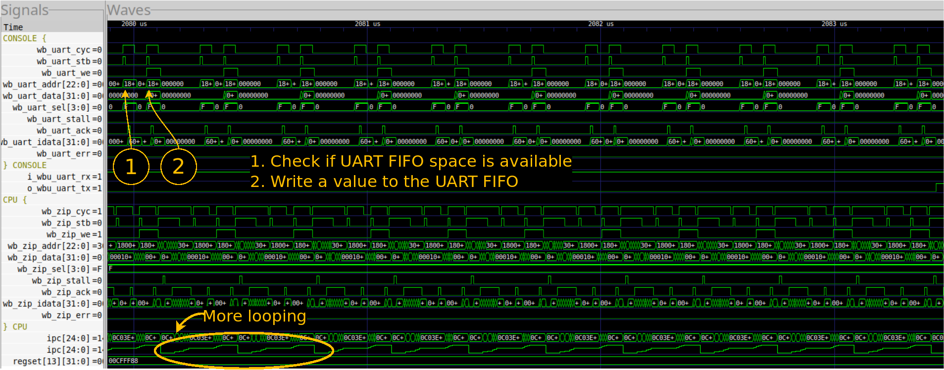 |
Now, if you look at the bus ports for the console, shown with the prefix
wb_uart_, you’ll see a repeating pattern of two requests. The first is
a read request, to verify that there’s room in the
serial port’s buffer
for another byte of data. The second is a write request, sending the next
byte to the buffer.
The big thing to learn here, if nothing else, is the utility of displaying the PC as an analog signal.
Debugging a memory value
One common problem I’ve run into is where you get deep into the standard library (i.e. into someone else’s software), and you see the CPU read some value from memory and then do the wrong thing. Or, rather, it does the right thing but with the wrong value. That leads to the question, why was that value wrong? When did it become wrong? These are both things you may need to answer.
I discussed how to find a bug like this in simulation. in a previous post.
What if you need to find this value while running from hardware?
Ouch. That’s harder. Still, the same approach applies: pick the address of interest, and track its value.
In hardware, this often means that you’ll need to create a bus monitor peripheral. That monitor peripheral will then look to find every time you write to a given address, and keep track of what the value at that address becomes when you write to it. Beware, inserting such a peripheral into your design might change your address map, so you might need to do a bit of rework, but the basic idea applies.
If your monitor detects a “wrong value” being written to the address of interest, then it should be able to halt the CPU–so you can see what just happened. Or, perhaps, you might wish to simply trigger a trace of the CPU to see what’s going on there.
If, on the other hand, you never write a “wrong value” to the address of interest, and yet still read a “wrong” value–then you know where to look: the memory controller for the memory you are writing to. You may need to initiate reads of this address at various other times–at least enough to narrow down and find when the value is changing. Is it changing via a bus write to some other address? That would be important to know. Is it not changing when it’s being written to? That would also be important. Finding out when, and the circumstances around it will be key to figuring this out.
Your eventual goal here will be to encapsulate the basic bug-triggering sequence so that you can trigger it in a much simplified setting–either with the debugging bus and not the CPU, or perhaps in simulation. From there, you should (hopefully) be able to get a trace in order to narrow it down further.
Conclusions
The big challenge with all of the above tasks is that you are likely going to be debugging someone else’s work: either their design or their software library. In my case, it’s my CPU but Xilins’x MIG controller is not my RTL, neither are newlib nor FATFS my software. Sure, it’s my CPU, but I didn’t design any of the other components on the circuit board, nor have I designed the external memory. If I want all of these components to work together in my project and for my purpose, then I need to know how to handle debugging them. This will often mean tracing through someone else’s software just to find the bugs in my own stuff.
What about Linux?
No, I haven’t gone back to the Linux operating system I tried to boot on the Beagle Bone. I’ve just had too many other paying opportunities to do something else, and I’ve now lost touch with the potential customer who may have wanted that system.
Still, if I needed to debug Linux, I think I’d use this same approach. The Linux kernel contains within it several simplified console output functions that can be used for debugging the kernel prior to the entire operating system being up and running. While I haven’t tried using these personally (yet), I’ve seen others do it to great success. Similarly, my Beagle Bone has a JTAG port that I could use instead of the debug bus. It’s not a one to one replacement, but my bet is that it will still be good enough.
In the beginning was the Word, and the Word was with God, and the Word was God. (John 1:1)